Generalized Anisotropic
The Generalized Anisotropic Strength option allows you to create a composite material model in which you can assign any strength model in RS2 to 1) any range of slice base orientations or 2) any set of anisotropic surfaces. For example, you could create a material with Hoek-Brown properties over a range of orientations or along a surface, and Mohr-Coulomb properties over another range of orientations or along a surface (e.g. to simulate a weak bedding orientation in a rock mass).
To define a Generalized Anisotropic Strength function set the Strength Type = Generalized Anisotropic in the Define Material Properties dialog. You will notice two Input Type options (or three if you have exported a Generalized Anisotropic model from Slide2 that was originally from Slide3), as explained below.
Input Type = Angle Range
This is the original Generalized Anisotropic function option. The user can input angle ranges and assign a material to each range.
Note
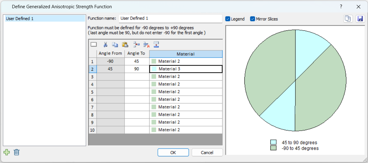
- The FIRST angular range always starts at –90 degrees (this is the default value of the FIRST Angle From value, and cannot be edited by the user).
- The angular ranges must be ordered counter-clockwise, from –90 to +90.
- The Angle From values cannot be edited, and are automatically defined by the Angle To value in the previous row.
- The LAST angular range always ends at +90 degrees (this must be entered by the user, as the LAST Angle To value).
- As the data is entered, the chart at the right of the dialog, will be updated to display the Generalized Anisotropic Function you are defining.
- Check the chart carefully, to make sure that you have defined the intended function (i.e. all angular ranges and materials are correct).
Input Type = Angle or Surface
Two additional methods of defining anisotropy are found within this option. For users of RS3/Slide3, this option will be recognizable as the Generalized Anisotropic strength function in RS3/Slide3. The inputs are outlined below.
- Base Material: this represents the strength properties of the rock mass, for failure planes which are not within the defined orientation range of the anisotropic plane(s) or surface(s).
- Anisotropy Definition: This can be angle or surface. The two are outlined in detail further down.
- Mapping Function: defines how the strength is determined for each slice bottom. Can only be A and B in RS2. More details further down.
Anisotropy Definition
Angle
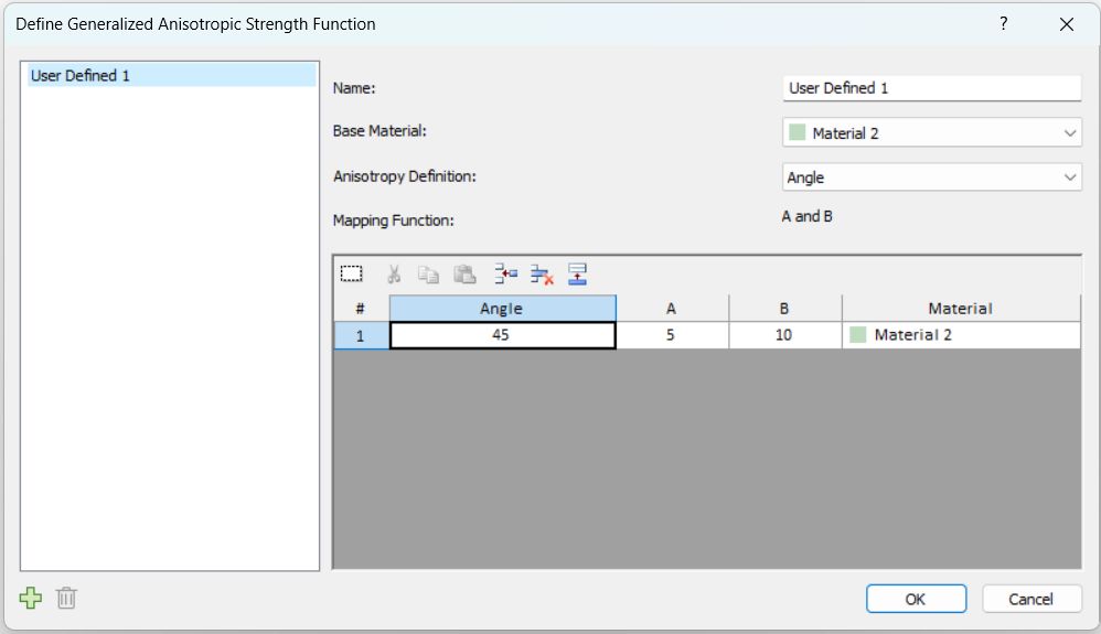
This is similar to the Input Type = Angle Range option, but with a list of different mapping functions to choose from. As an example, we will explain the meaning of the previous image. In the function, the user has set the base material to Material 2, and defined an angle of 45 degrees for Material 3. This means that if the slice base falls along a 45 degree angle, the strength of Material 3 will be applied. If the slice base is orthogonal to this, the strength of Material 2 will be applied. What happens in the angle range in-between is defined by the Mapping Function selection (more details further down).
Surface
This option allows the user to define multiple anisotropic surfaces and assign different materials to each one. The point on the anisotropic surface that is closest to the given slice base is found, and the angle of the anisotropic surface at that point is taken as the angle of anisotropy for the given slice base. Once the angle is obtained, the calculations proceed as explained in the previous section.
The way the Anisotropic Surface works is explained in detail in the Anisotropic Surface Overview topic. Note that you must first use the Add Anisotropic Surface option to define an anisotropic surface before being able to access this option.
Mapping Function
A and B
A and B define discrete ranges over which the strengths of the different joints are applied or interpolated. As an example, we will refer back to the dialog image further up, and explain the meaning. In this case, Mapping Function is set to A and B.
In the function, the user has set the base material to Material 2, and defined an angle of 45 degrees for Material 3. This means that if the slice base falls along a 45 degree angle, the strength of Material 3 will be applied, otherwise the strength of Material 2 will be applied.
However, so as not to be so limited to the exact 45.0 degree angle, the A and B values are used to provide a range. The A value means that Material 3 will be applied within the range of [Angle +/- A], or [45 +/5]. The B value means that the strengths of the base material and Material 3 will be interpolated in the ranges [Angle + A, Angle + B] and [Angle - A, Angle - B], or [45+5, 45+10] and [45-5, 45-10]. In summary the above screenshot can be translated to this definition of anisotropy:
- Strength of Material 3 is applied for slice base in these angle ranges:
- [40, 50]
- Strength of Material 2 is applied for slice base in these angle ranges:
- [-90, 35]
- [55, 90]
- Interpolated strength of Material 2 and Material 3 is applied for slice base in these angle ranges:
- [50, 55]
- [35, 40]
A and B are explained in more detail in the Anisotropic Models manual.
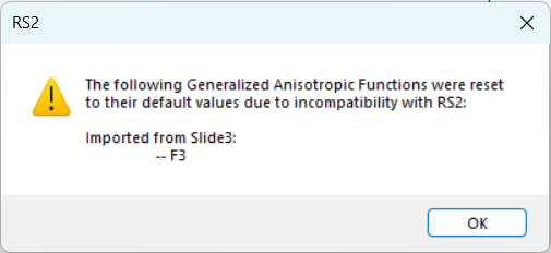
Slide2 and Slide3 provides two additional mapping functions, Linear and Cosine, which are not supported in RS2. These materials will be reset to A and B during import into RS2, and a warning message will appear, as below.
For more details on Mapping Functions in Slide2 and Slide3, see their topics.
Input Type = Imported from Slide3
This option is available only for the Generalized Anisotropic materials that were originally created in Slide3, and that Slide3 model was exported through Slide2 into RS2. It means the RS2 model must follow this pathway:
- Export Slide3 model to Slide2
- In Slide3, open a computed Slide3 model that uses Generalized Anisotropic materials.
- Select Interpret > Create 2D Sections through Global Minimums. In the prompted “Slide2 Section Creator” dialog, create a Slide2 section.
- Select Analysis > Slide2 Integration > Compute/Export to Slide2. In the prompted dialog, select a Slide2 section to export.
- The model will automatically open in Slide2. Save the Slide2 file (.slmd)
For more details, see the tutorial Generalized Anisotropy – Exporting from Slide3 to Slide2 and the Slide2 topic Generalized Anisotropic, under the section: Input Type = Imported from Slide3.
- Import Slide2 to RS2
- In RS2, import the Slide2 file by selecting File > Import > Import Slide, or simply drag the Slide2 file to RS2 modeler.
Continue with the imported model, select Properties > Define Materials, and navigate to the Strength tab. For the generalized anisotropic material, you should see Failure Criterion = Generalized Anisotropic, Input Type = Imported from Slide3, as below.
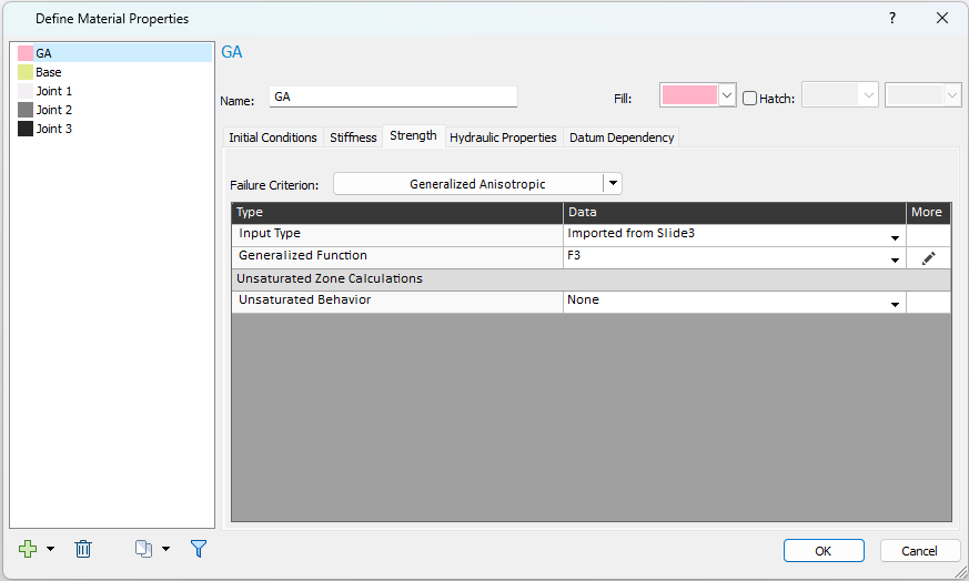
Select the Edit  button to open the Define Generalized Anisotropic Strength Function dialog, as below.
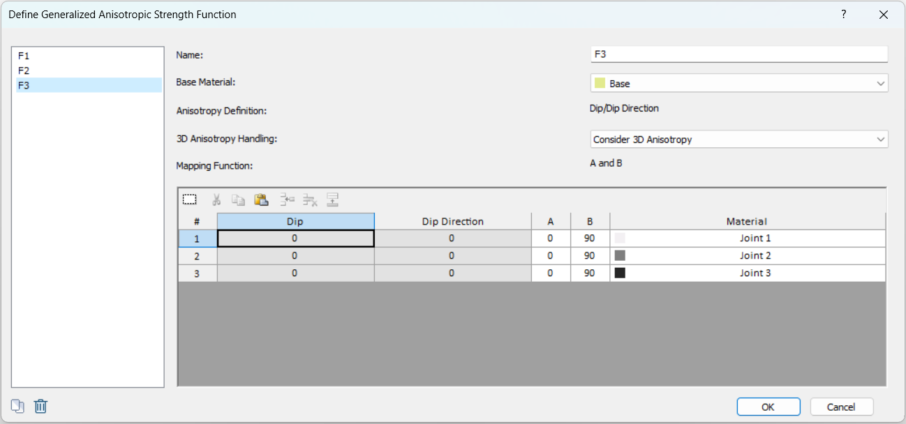
Anisotropy Definition
Slide3 provides two options for Anisotropy Definition: Dip/Dip Direction and Surface. For materials imported into RS2 from Slide3, only Dip/Dip Direction is supported.
3D Anisotropy Handling
One more option is added to the dialog, 3D Anisotropy Handling, with two methods: Consider 3D Anisotropy and Consider Apparent Dip.
- 3D Anisotropy Handling = Consider 3D Anisotropy
- This is the default. It means the 3D dip and dip direction values will be considered in the analysis.
- 3D Anisotropy Handling = Consider Apparent Dip
- This option creates a pure 2D analysis. The 3D orientations will not be considered.
- By choosing this option, the Anisotropy Definition will automatically change from Dip/Dip Direction to Angle, and only the apparent dip value (the projected angle of anisotropy on the 2D section) will be considered as the anisotropic angle.
Mapping Function
Similar to regular GA materials in RS2, the only Mapping Function supported is A and B. See details in above section.
Notes
- For more details on the Generalized Anisotropic in Slide2 and Slide3, see their topics.
- The Dip, Dip Direction, A, B, values are the 3D values from the Slide3 model.
- IMPORTANT: Using the A and B mapping function with narrow A and B values, while using the "Consider 3D Anisotropy" option may make it difficult for the slice bases on the 2D section to fall in the A and B ranges. In this case, the 2D section slice bases will fall in the rock mass orientations. For a proper results comparison, keep a wide range in all the Slide3, Slide2, and RS2 model.
Additional Notes
A Generalized Anisotropic material (herein referred to as the "parent" material) can be defined to have differing base and joint material properties, which are herein referred to as "child" materials.
- The functions defined with each input type create two separate lists. For example you may have a list of two functions defined with Input Type = "Angle Range" which you can access from the dropdown when the Angle Range type is selected. You will see a different list and set of functions when the Input Type = Angle or Surface is selected.
- You cannot assign a Generalized Anisotropic function to itself.
- With Input Type = "Angle Range", no interpolation of material strengths occurs as does with the other Input Type on account of A and B. As a result, the water properties are used differently. Input Type = "Angle Range" uses the water properties of the child material that is used in the given angle range. Input Type = "Angle or Surface" uses the water properties of the parent material (the Generalized Anisotropic material itself)
- The unit weight of the parent material will be used to calculate the weight of a slice.
- The design factors specified in the Project Settings relating to material strength will be applied onto the child materials.
- Due to the algorithmic difference between the two Input Types, equivalent anisotropic definitions in the two types may exhibit a negligible numerical difference in FS.