Joint Model: Parallel Deterministic
The Parallel Deterministic joint network model allows you to define a network of parallel joints with a fixed spacing and orientation. In this case deterministic refers to the fact that the spacing, length and persistence of the joints is assumed to be constant (i.e. exactly known with no statistical variation). However, the Parallel Deterministic model does allow randomness of the joint location, as discussed below.
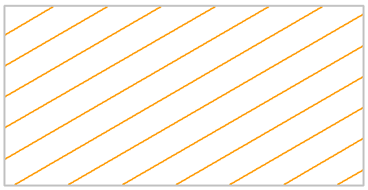
Parallel Deterministic joint network with infinite joint length, 30 degree inclination
The following input parameters can be defined for the Parallel Deterministic joint network model.
Orientation
Use Trace Plane
The Trace Plane as defined in the joint network dialog, is simply the cross-sectional plane of your RS2 model.
Depending on the setting of the Use Trace Plane option, the joint orientation and spacing can be defined using strictly 2-dimensional input with respect to the Trace Plane, or 3-dimensional measurements can be accounted for, as described below.
Use Trace Plane = No
If Use Trace Plane = No, then the input is strictly 2-dimensional. The inclination (and spacing) of the joints is measured in the 2-dimensional cross-sectional plane of the RS2 model.
Use Trace Plane = Yes
If Use Trace Plane = Yes, you will be required to enter the 3-dimensional orientation and spacing of the joint planes, and the trace plane orientation. RS2 will then use this 3-dimensional input to determine the 2-dimensional traces of the joint planes on the trace plane. If you are using this option, it is important to note the following:
- The Trace Plane is assumed to be vertical (i.e. Dip = 90 degrees). Therefore only the Trace Plane Dip Direction is required. This is the direction (i.e. trend or azimuth) of the normal vector of the Trace Plane, measured clockwise from north. Also note, the normal vector is assumed to be pointing INTO the screen (i.e. away from the viewer).
- The Dip and Dip Direction of the joint planes follow the standard definition, although only positive values are allowed.
- RS2 uses the 3-dimensional input to determine the 2-dimensional traces of the joint planes on the trace plane.
- The joint spacing (see next section) is the actual, 3-dimensional spacing between the joint planes (i.e. the true perpendicular distance between the parallel joint planes, as measured in 3-dimensions).
- The resultant joint plane spacing that you will see on the trace plane, will in general be GREATER than the true spacing, if the joint planes intersect the trace plane at an angle of less than 90 degrees. The apparent (2D) spacing will be equal to the true (3D) spacing, only if the joint planes are exactly perpendicular to the trace plane.
- The joint planes cannot be exactly parallel to the trace plane, because then it is impossible for them to intersect the trace plane. A warning message will be displayed if this occurs.
Remember that the RS2 plane strain analysis is 2-dimensional. When you enter the 3-dimensional joint plane orientations, you are NOT defining a 3-dimensional joint network. RS2 only uses the 3-dimensional information, to determine the 2-dimensional traces of the joint planes on the trace plane. Once this has been determined, the actual analysis is 2-dimensional (i.e. the model will behave as if the joints were perpendicular to the trace plane).
Inclination
If Use Trace Plane = No you will be required to enter the joint plane Inclination.
The Inclination is the angle of the joint planes as measured from the x-axis of the model. Values can range between -90 degrees and 90 degrees.
Trace Plane Dip Direction
If Use Trace Plane = Yes you will be required to enter the Trace Plane Dip Direction. See above for details.
Dip / Dip Direction
If Use Trace Plane = Yes you will be required to enter the joint plane Dip and Dip Direction. See above for details.
Spacing
The Spacing is the perpendicular distance between the parallel joint planes. For the Parallel Deterministic joint network model, the spacing is a constant value (i.e. equal spacing between all joint planes).
It is important to note that the definition of spacing depends on the setting of the Use Trace Plane option (see above for details).
- If Use Trace Plane = No, then the spacing is measured in the 2-dimensional cross-sectional plane of the RS2 model (i.e. the apparent spacing, as measured on the trace plane).
- If Use Trace Plane = Yes, then the spacing which you must enter is the actual, 3-dimensional spacing between the joint planes (i.e. the true perpendicular distance between the parallel joint planes, as measured in 3-dimensions).
In general, the apparent (2-dimensional) joint spacing will be GREATER than the actual (3-dimensional) joint spacing. The apparent spacing will be equal to the true spacing, only if the joint planes are exactly perpendicular to the trace plane.
Initial Location
For the Parallel Deterministic model, the location of the joint network can be randomly generated, or can be forced to go through a user-defined point.
- If Random Location = Yes, then RS2 will randomly generate the position of the joint network (i.e. although the joint spacing, orientation and length are fixed, the position of the joint network is randomly generated). If you are not happy with the results, you can select the Randomize button (see below) to generate a new joint network.
- If Random Location = No, then you will be able to enter an X,Y coordinate pair, and the joint network will be forced to go through this point (i.e. one of the joint boundaries will pass through the specified point). This is useful if the actual location of the joints is known.
NOTE: if you select the Randomize button in the Joint Network dialog, the location of the joints will be updated, if applicable.
Length
For the Parallel Deterministic model, the joint length can be specified as infinite, or discontinuous (i.e. given a user-defined length and persistence).
- If Infinite Length = Yes, then the joints will extend continuously across the region.
- If Infinite Length = No, then you can specify the joint length, persistence and random offset, as described below.
Length
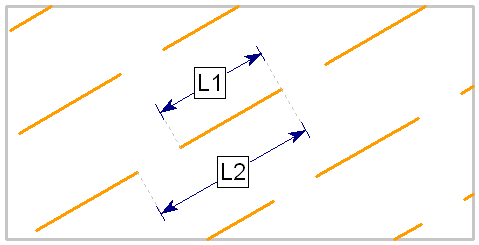
The Length defines the length of each individual joint in the network, as measured in the plane of the model (i.e. the trace plane). For the Parallel Deterministic model, all joints in the network will have the same length. In the figure below, the joint length is given by the distance L1.
Persistence
The Persistence is defined as the ratio of joint length to total length along any joint plane, as illustrated in the following figure (Persistence = L1 / L2). The Persistence is a measure of joint continuity along a given plane. For example, if Persistence = 0.5, then the joint length is equal to 50% of the total length.
For the Parallel Deterministic model, the Persistence is a constant value, and defines a uniform length of intact material between each joint segment. In the following figure the Persistence = 0.7. The Persistence value entered in the dialog must be greater than 0 and less than 1 (Persistence = 1 implies 100% continuity in which case you would use the Infinite Length = Yes option).
Definition of joint persistence = L1 / L2
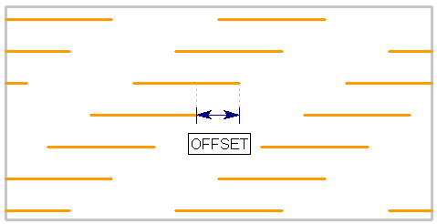
Random Offset
The Random Offset option allows you to specify a random or uniform offset between the ends of joint segments on adjacent joint planes.
- If Random Offset = Yes, then RS2 automatically generates a random offset between the ends of adjacent joint segments on adjacent planes. This creates an overall random pattern for the joint network.
- If Random Offset = No, then you will be able to input an Offset Length, which will define a uniform offset between the ends of joint segments on adjacent planes. This gives a repeating, uniform pattern to the joint network, as illustrated in the following figure.
Definition of offset length for parallel joint network
Joint End Condition
For a description of the Joint End Condition option, see the Add Joint Network topic. For further information see the Add Joint Boundary topic.
Randomize
The Parallel Deterministic model is not entirely deterministic, and allows randomness with respect to the location of the joints in the network. If you wish to re-generate the joint network you can select the Randomize button.
The Randomize button will randomly re-generate the joint network, according to the following settings in the joint network dialog:
- If Infinite Length = Yes and Random Location = Yes (or)
- If Infinite Length = No and Random Location = Yes (or)
- If Infinite Length = No and Random Offset = Yes
If any of the above selections are in effect, then new joint locations will be generated each time you select the Randomize button. If none of these selections is in effect, then the position of the joint network is entirely fixed, and the Randomize button will have no effect, for the Parallel Deterministic model.
See the Add Joint Network topic for more information about the Randomize option.