Define Hydraulic Properties
The Define Hydraulic Properties  option, located in the toolbar or through Properties menu, allows you to specify the groundwater/hydraulic parameters for each material. This dialog is only applicable if pore pressure is considered in your RS2 analysis (i.e. using Piezometric Lines, Water Pressure Grids, Ru values, or finite element seepage analysis). If you are NOT considering pore pressure in your analysis, this dialog is unnecessary.
Options in this dialog are determined by the Groundwater Method selected in the Project Settings menu. This page covers options for Groundwater Method = Static.
- If the Groundwater Method = Finite Element Analysis, additional saturated and unsaturated permeability characteristics can be defined. See the Hydraulic Properties (Seepage Analysis) topic for details.
- The materials in the Define Hydraulic Properties dialog correspond to the materials in the Define Material Properties dialog (i.e. the dialog in which you define the strength properties of your materials).
- The material names and colours which appear in the Define Hydraulic Properties dialog are those which are specified in the Define Material Properties dialog. The names and colours CANNOT be edited in the Define Hydraulic Properties dialog -- if you wish to edit the name or colour of a material, this must be done in the Define Material Properties dialog.
Material Behaviour
You can define the Material Behaviour as Drained or Undrained.
- For more information about undrained behaviour modelling, see the Undrained Behaviour of Soil topic.
- Alternative to by material, the drained/undrained behaviour can also be set by stages for consolidation analysis. See the linked topic for more information.
Fluid Bulk Modulus
The fluid bulk modulus (![]() ) refers to the compressibility of a fluid. It describes the volume change as results of pressure changes.
) refers to the compressibility of a fluid. It describes the volume change as results of pressure changes.
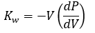
 is the initial volume of the fluid and
  is the rate of change of pressure with respect to volume.
Biot's Coefficient Calculation Method
You can choose how the Biot’s Coefficient (α) is determined for calculating effective stress:
- Auto
- The Biot’s coefficient value is automatically calculated using the formulas.
- Custom
- Define a Biot’s coefficient value within the range [0,1).
- Off
- Assumes the solid material is incompressible (α = 1).
Biot's Coefficient
Biot’s Coefficient, the ratio of the fluid volume change in a solid material to the volume change of that material when the pore pressure is changed, is calculated as:

 is the bulk modulus of the drained porous medium taken as
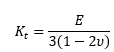 and
and is the bulk modulus of the skeleton. In RS2,is taken as 69000 MPa as suggested by Terzaghi.
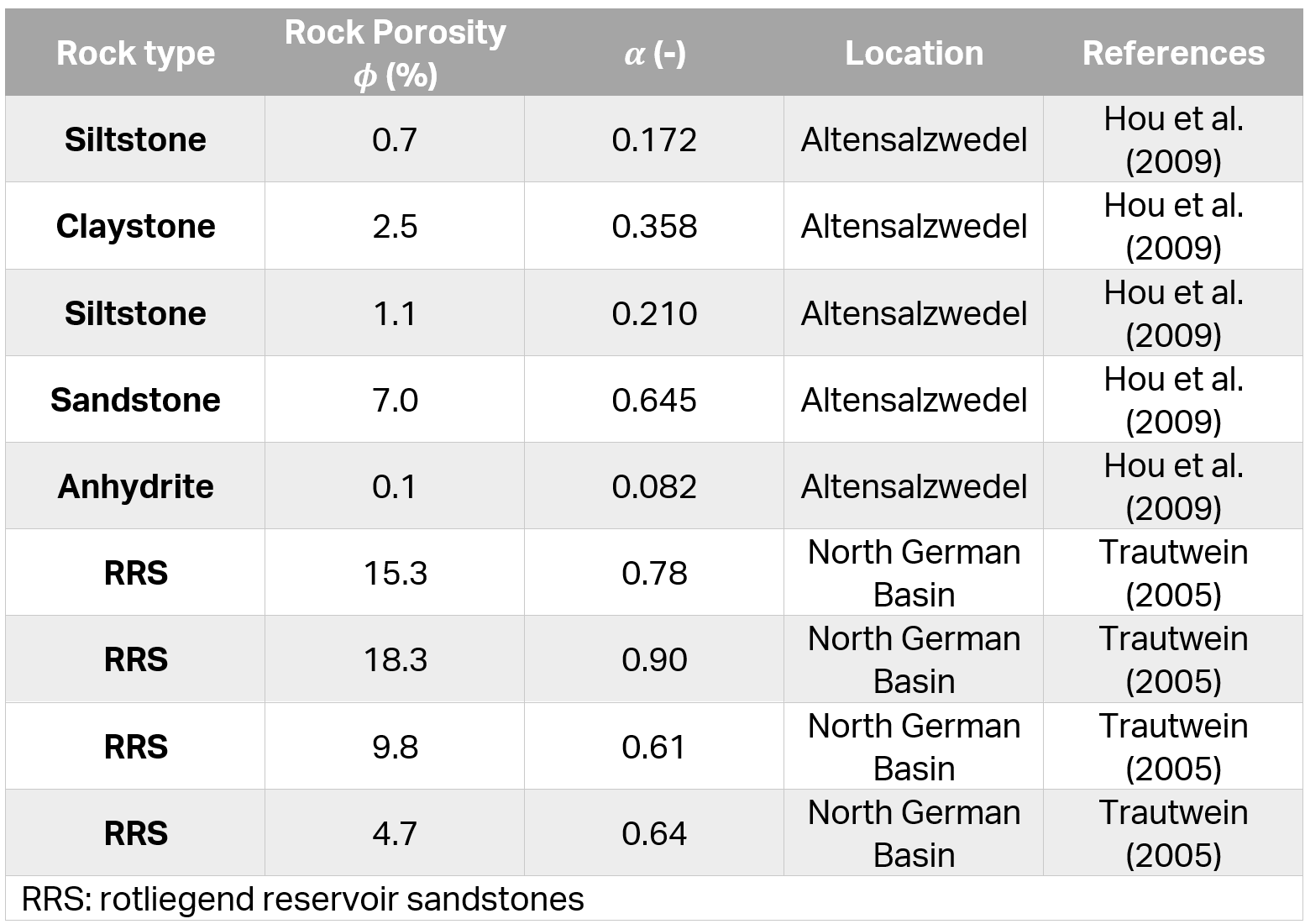
For most soil types, the value of α will be around 1. However, the α values for hard rocks may vary. Some typical values of α for rocks can be found in Table 1 below (Luo et al, 2015).
Biot's Coefficient in effective stress calculation
Without the Biot’s Coefficient (α), the effective stress (![]() ) calculations for saturated and unsaturated materials are:
) calculations for saturated and unsaturated materials are:
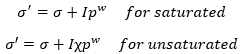
With the Biot’s Contant (α), the calculations are:
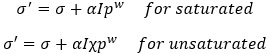
 is the total stress,
  is the suction,
  is a coefficient for unsaturated single effective stress calculation, and
  is the unit matrix
For more information about Biot’s Coefficient for effective stress calculation in undrained materials, see the link.
Legacy
Versions 11.022 to 11.027
In these versions, Biot’s coefficient was primarily controlled by the “Use Boit’s Coefficient for calculating Effective Stress” toggle option.
 button on the groundwater Project Settings page, where either an auto-calculated or user-defined value could be used.
Versions Earlier than 11.022
button on the groundwater Project Settings page. This setting applied only to coupled consolidation analyses.Piezo to Use
Piezometric Lines are created with the with the Add Piezometric Line option. Each Piezometric Line has an ID number associated with it. These ID numbers are automatically created by RS2, when the Piezometric Line is added to the model.
- In order to assign a Piezometric Line to a given material, select the ID number of the desired Piezometric Line from the Piezo to Use drop-list. The selected Piezometric Line will then be used for the pore pressure calculations for that material.
- If you want to specify zero pore pressure for the material then select Piezo to Use = None.
- If Piezo to Use = None, you can specify an Ru value to calculate pore pressure for the material, see below.
Note: the Piezo to Use option is applicable if you want to use ONE Piezometric Line for the pore pressure calculation for a given material, AT ALL STAGES OF THE MODEL (for staged models). If you require different piezo lines to be applied at different stages, then use the Stage Piezo Lines option described below.
Stage Piezo Lines
If your model consists of multiple stages, and you require different piezo lines to be applied at different stages, for a given material, then use the Stage Piezo Lines option. This allows you to simulate, for example, the draw down of a water table at different stages.
To assign the staging of Piezometric Lines:
- In the Define Hydraulic Properties dialog, select the Stage Piezo Lines check box.
- You will notice that the Piezo to Use option becomes disabled, and the area below the Stage Piezo Lines check box becomes enabled.
- Now select the Add Stage button, until the number of rows is equal to the number of stages at which you need to specify a Piezometric Line. For example:
- If you need to assign 3 Piezometric Lines at 3 different stages, then select Add Stage TWICE, so that a total of 3 rows appears in the data entry area below the Stage Piezo Lines check box.
Note: if the Add Stage button is disabled, this means that you have not set the Number of Stages in Project Settings. In this case, go to the Project Settings dialog, and define the number of stages.
- In each row, enter the Stage number at which the Piezometric Lines are to be assigned.
- In each row, select the Piezo ID number representing the Piezometric Line that you wish to assign at the specified stage.
- It is important to note that you only need to define the Stage and Piezo ID information, for the stages at which the Piezometric Line will change. You DO NOT need to define this information at stages where the Piezometric Line does not change.
- If you accidentally add too many rows with the Add Stage button, click the mouse in a row and select the Delete Stage button, to delete the row.
- When you are finished entering the Stage and Piezo ID numbers, if your model consists of multiple materials with the same staging of Piezo Lines, you can use the Copy To button to automatically copy the Stage / Piezo ID information to other materials in the dialog (see below).
- When the analysis is run, RS2 will use the Stage and Piezo ID information in the Define Hydraulic Properties dialog, to determine the correct Piezometric Line to be used at each stage of the analysis, for each material.
Note: you can use the View Piezos by Stage option to view only the piezo line(s) which are applicable for the current stage. This allows you to easily verify that the correct staging sequence of the piezometric lines has been applied.
Hu Value
The Hu value is simply a factor between 0 and 1, by which the vertical distance from a point (in the soil or rock), to a Water Surface (i.e. Piezo Line) is multiplied to obtain the pressure head. The Hu value is used to calculate pore pressure as follows:
u = ywhHu
where:
u = pore pressure
yw = the Pore Fluid Unit Weight (entered in the Project Settings dialog)
h = the vertical distance from a point to a Piezometric Line
Hu = the Hu value for the material
Note: if the distance h is negative, (i.e. a point is above the Piezometric Line) then the pore pressure is set to zero at that point.
There are two ways of defining the Hu value - Auto or Custom.
CUSTOM HU
With the Custom option, the user can enter their own value for Hu. A value between 0 and 1 is usually specified. For example:
- Hu = 1 would indicate hydrostatic conditions. This can be used where the Water Surface is horizontal. Where the Water Surface is inclined, setting Hu = 1 will (in general) provide a conservative (high) estimate of the true pore pressure.
- Hu = 0 would indicate a dry soil. Pore pressure will be zero. Setting Hu = 0 can be used to turn "off" the pore pressure for a material, although this can also be achieved by setting Piezo to Use = None.
- Intermediate values of Hu can be used to simulate head loss due to seepage. This would be applicable where the Water Surface is inclined. NOTE: the Auto Hu option, described below, can be used to automatically account for the inclination of the Water Surface.
AUTO HU
With the Auto Hu option, RS2 will automatically calculate a value of Hu, based on the inclination (angle) of the Piezo Line, above a given point. This is based on the assumption that the equipotential line which passes through the point, is a straight line between the point and the Piezo Line (strictly applicable for an infinite slope case). This is illustrated below.
a = the inclination of the Water Surface (above a given point)
h = vertical distance from the point to the Water Surface
Simple geometry can be used to show that the pressure head, as illustrated in the diagram below, is equal to h cos2a. The automatically calculated Hu coefficient, is therefore equal to cos2a. For a horizontal Water Surface, a = 0, and Hu = cos2a = 1.

Automatic Calculation of Hu coefficient
The Auto Hu option is a simple method of estimating pore pressures, based on the inclination of a Water Surface. In the absence of more accurate data (e.g. Seepage Analysis results), this is a simple but useful method of approximating head loss due to seepage.
Ru Value
An Ru value simply models the pore pressure as a fraction of the vertical earth pressure. The vertical earth pressure is estimated from the unit weight and height of each material directly above a given point. The Ru Value is normally between 0 and 1.
An Ru Value can be specified for a material under the following conditions:
- If the Groundwater Method = Piezometric Lines in Project Settings, and Piezo to Use = None in the Define Hydraulic Properties dialog, then you can enter an Ru value for the material.
- If the Groundwater Method = Water Pressure Grid in Project Settings, and Grid to Use = None in the Define Hydraulic Properties dialog, then you can enter an Ru value for the material.
If one soil type has regions of differing Ru values, then a different material will have to be defined for each different Ru value. Appropriate material boundaries will have to be added to the model, in order to define the different soil regions.
Grid to Use
If you are using water pressure grids to define pore pressure, the Grid to Use option allows you to select a water pressure grid to use for a material.
- If you have multiple grids defined, choose the name of the desired grid.
- If you want to specify zero pore pressure for the material then select Grid to Use = None.
- If Grid to Use = None, you can specify an Ru value to calculate pore pressure for the material (see above).
- If you want to stage pore pressure using multiple grids, then select the Stage Grids check box (see below).
Stage Grids
If you have multiple water pressure grids defined, and you want to apply different grids at different stages, select the Stage Grids check box, and define the staging of the grids.
The Stage Grids option works in exactly the same way as the Stage Piezo Lines option described above.
Copy To
The Copy To ![]() option allows you to define the groundwater/hydraulic information for one material, and then automatically copy the same information, to any other materials in the model. This is useful when all or most of the materials in a model, have the same groundwater conditions (for example, they all use the same piezo line).
option allows you to define the groundwater/hydraulic information for one material, and then automatically copy the same information, to any other materials in the model. This is useful when all or most of the materials in a model, have the same groundwater conditions (for example, they all use the same piezo line).
The Copy To option is particularly useful if you are using the Stage Piezo Lines or Stage Grids options. The staging information can be defined once, and copied to other materials. For example:
- Define your Piezometric Line staging information for ONE material.
- Select Copy To. In the Copy Material Properties dialog, select the materials to which you would like to copy the information, and select OK.
- The Copy To option also copies the Hu value for the current material, to the selected materials.
Stage Hydraulic Properties
For a multi-stage model, hydraulic properties can be staged in the Stage Factors tab, under the Stage Hydraulic properties and
Stage Hydraulic Distributions categories. See the Stage Factors topic for more information.