Add Liner Connection
The Add Liner Connection option allows you to assign a hinge to connect liners, instead of a node of mesh. A hinge can be applied to the liner node that connects two liners together. The hinge can be either a zero bending moment hinge, or a plastic hinge that contains a moment capacity.
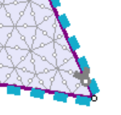
Display of a Liner Connection
NOTE: Liner Connections can only be applied if the finite element mesh exists, and two liner elements are connected. By saying liner element, it includes any of a liner, composite liner, or structural interface in RS2. Note that a liner element in RS2 is also referred to as a "beam" or "beam element" since liners are modeled using beam elements on the excavation boundaries. Otherwise, the Liner Connection option will not be available.
To add a liner connection:
- Select Add Liner Connection
 from the Liner Moments sub-menu of the Loading menu.
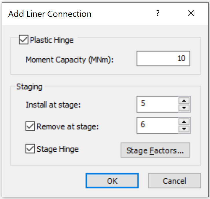
- Plastic Hinge:
- The Liner Connection can be assigned as a Plastic Hinge which contains a defined Moment Capacity value. To do this, select the checkbox for the Plastic Hinge option, and enter a value for the Moment Capacity. If this option is not selected, the liner connection will be a hinge with zero moment, which allows the liner to freely rotate at that point.
- Staging:
For a multi-stage model, you are allowed to specify the installation stage of the Liner Connection(s). You can also specify a removal stage, by selecting the Remove at stage check box and entering the stage at which the Liner Connection(s) are to be removed (uninstalled).
Stage Hinge
On a multi-stage model, Moment Capacity of the hinge can be staged by selecting the Stage Hinge check box, and selecting the Stage Factors button. In the Stage Factors dialog, you can enter a Factor for the hinge at each stage.
In the Stage Factors dialog, you can stage the liner connection properties. For each stage, you can decide whether the hinge will be plastic, and enter a Factor for the moment capacity.
Factor = 1 means that the stiffness will be equal to the magnitude(s) entered in the Add Liner Connection dialog.
You can increase or decrease the magnitude of the moment capacity at any stage, by entering a Factor greater than or less than 1 (e.g. a Factor = 2 would double the capacity). Factor = 0 means that the moment capacity will be 0 for the stage.
If you want to apply different factors to normal and shear stiffness, select the Different stage factors check box to do so.
- If your model is single stage, the Staging section will not be available, proceed directly to Step 4.
- Select [OK] when you have specified the staging information.
- Use the mouse to select a vertex between two liner elements (liner, composite liner, or structural interface), on which to apply a Liner Connection. When nodes are selected, they will be highlighted by a small circle. Press Enter.
- Use the mouse to select a boundary segment on an liner element (liner, composite liner, or structural interface). Press Enter or right-click and select Done Selection. The Liner Connection will be applied to the selected node on the side of selected segment, as you will see a Liner Connection symbol on the segment close to the node.
- The Liner Connection will be added as an item under Loading > Liner Connections in the Visibility Tree. Its properties will be displayed in the dock panel below, under the Properties section.
NOTE: if you specified installation and/or removal stages in the Add Liner Connection dialog, the hinges are only displayed at stages where they exist (i.e. a Liner Connection will NOT be displayed if the viewed stage is LESS THAN the installation stage or GREATER THAN OR EQUAL TO the removal stage).
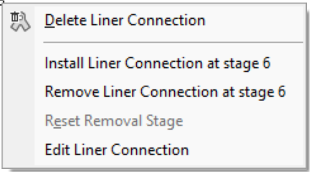
Right Click Shortcut
Right click on the Liner Connection in the model for shortcut options as shown below.
- Delete Liner Connection
- Install Liner Connection at stage x
- Remove Liner Connection at stage x
- Edit the staging at the current stage
- Reset Removal Stage
- Available if the Remove at Stage option is selected. By selecting Reset Removal Stage option, the Remove at stage option will be unselected.
- Edit Liner Connection
- Go to the Edit properties dialog