Axisymmetric Analysis
In the Project Settings dialog, two different types of analysis can be selected - Plane Strain or Axisymmetric analysis.
The Axisymmetric option allows you to analyze a 3-dimensional excavation which is rotationally symmetric about an axis. The input is 2-dimensional, but because of the rotational symmetry, you are in fact analyzing a symmetric 3-dimensional problem.
A typical use of the Axisymmetric modeling option is to analyze the stress state around a circular shaft. See the RS2 Tutorials section for a tutorial on Axisymmetric modeling.
Some simple Axisymmetric models are shown below. Only an External boundary is required, the shape of the External boundary implicitly defines the excavation.
Examples of Axisymmetric models: if the left edge of each mesh is coincident with the X = 0 axis, then the model on the left represents a SPHERE and the model on the right represents a CYLINDER, in three dimensions.


The mathematical formulation of an Axisymmetric finite element is actually similar to Plane Strain (and plane stress) problems. By symmetry, the two components of displacement in any plane section of the excavation through its axis of symmetry define completely the state of strain, and therefore, the state of stress. Instead of analyzing a unit out-of-plane depth, the analysis is performed on a unit radian.
Restrictions on Axisymmetric Modeling
There are several restrictions on the use of Axisymmetric modeling in RS2:
- The Field Stress must be axisymmetric i.e. aligned in the axial and radial directions. Out-of-plane (or circumferential) field stress exists, but is equal to the radial stress, and cannot be independently varied.
- Cannot be used with Bolts (however Liners with elastic properties are permitted).
- All materials must have Isotropic elastic properties (cannot use Transversely Isotropic or Orthotropic elastic properties).
- The true orientation of your excavation can be arbitrary (i.e. it could be horizontal, vertical or at any inclination). However, for the purposes of the RS2 Axisymmetric analysis, you will have to map your coordinates so that the model is symmetric about the X = 0 axis (i.e. a vertical axis located at X = 0), since all finite elements are rotated about this axis.
- To form a closed excavation, one edge of your mesh must be coincident with the X = 0 (vertical) axis. If this is not the case, the excavation will be "open-ended".
- Most other RS2 modeling options can be used with an Axisymmetric model, however, always keep in mind the nature of an Axisymmetric model (for example, when defining loads, boundary conditions, etc.)
NOTE: As of RS2 version 9, joints can be used with Axisymmetric models. This includes joint boundaries, as well as joints associated with Composite liners or structural interfaces.
Interpret Axisymmetric Model Results
An example is modelled to interpret axisymmetric model results in RS2 and RS3.
This example is a 10m depth hollow circular shaft consisting of liners supported internal surface. Two type of forces are applied to the liners: a 0.1 MN/m hoop force (circumferential force) along the liner depth, and a 0.1 MN/m axial force around the internal circumference of the shaft top. The shaft has a 2 m internal radius and an 8 m external radius (see the Figure 1 below).
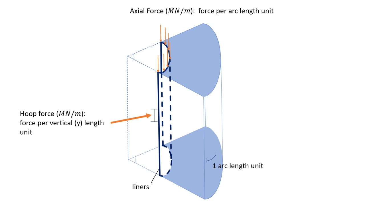
Figure 1. Hollow Circular Shaft Model Diagram
As shown in Figure 1 above, the hoop force is per unit of length in vertical direction along shaft depth (m). The axial force is per unit of arc length (m).
RS2 Model
The RS2 model is created using Axisymmetric Analysis (see Figure 2). The hoop force is 0.1MN per meter of arc length (out of plane) and per meter in y direction. The axial load is 0.1MN per meter of arc length (out of plane).
Hoop Force Results in RS2
In RS2 Interpret, the “Hoop Axial Force” is the hoop force. “-0.2 [MN/m] Hoop Axial Force” means -0.2 MN hoop force along the liner, and the unit is per m length. Model and results are shown in Figure 3 below.
Axial Force Results in RS2
The axial force results are shown in Figure 4 below. The axial force is 0.1 MN per m of arc length (out of plane).
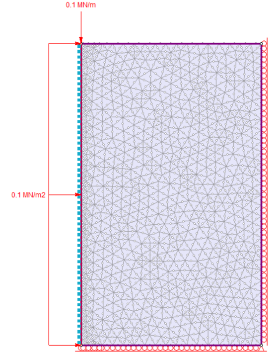
Figure 2. RS2 shaft model
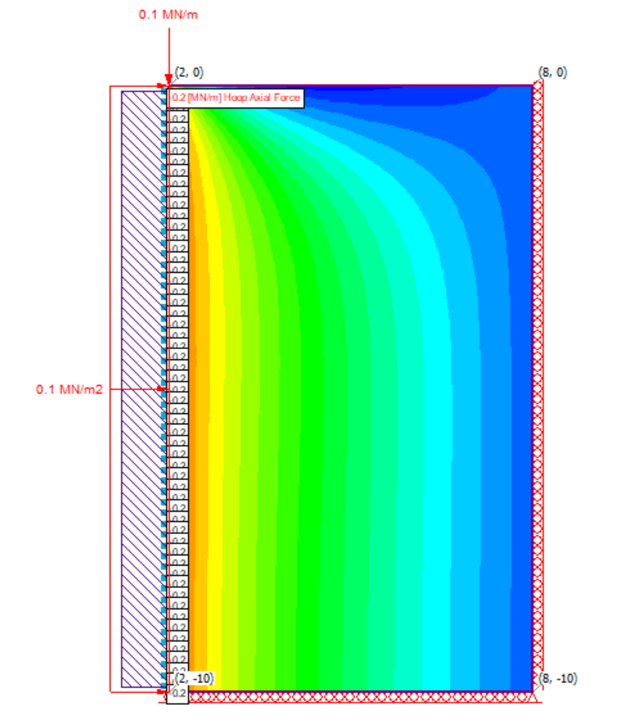 | 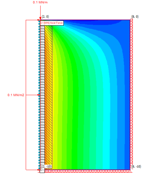 |
Figure 3. RS2 liners hoop force results (x=2, y=0 to -10) | Figure 4. RS2 liners axial force results (x=2, y=0 to -10) |
RS3 Model
In RS3, the hoop force is 0.1MN/m2, meaning 0.1 MN magnitude force acting over the area of 1 m arc length (in XY plane view) times 1 m depth along the liner in z-direction. The axial load is 0.1MN/m, meaning 0.1MN per m of arc length (in XY plane view).
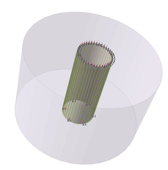
Figure 5. RS3 shaft model
Hoop Force Results in RS3
The contour result of Axial Force Y for Liners is displayed on XZ plane view, as shown in Figure 6 below. Here, the “Axial Force Y” indicates the hoop force.
Note: In real life, hoop forces are always acting normal to the surface. However, since RS3 follows a global coordinate system, the hoop force is acting normal to the two sides of inner shaft surface (along z at x=2, y=0, and x=-2, y=0), while it is acting tangential to the surface along z at x=0, y=0.
Thus, the two sides of the inner shaft data will be taking account for the liners hoop force data, which is -0.2 MN/m shown as blue contoured area. Here, -0.2 MN/m means -0.2 MN hoop force along the liner, and the unit is per m length.
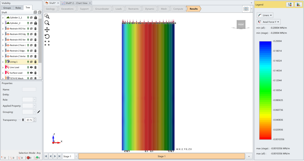
Figure 6. RS3 liners hoop force results (x=2, y=0, z=depth)
Axial Force Results in RS3
In RS3, the axial force results can also be shown by setting Element Type = Liners and Data Type = Axial Force Z. As seen in Figure 7 below, the axial force on liners is 0.1 MN/m, which means along the liners, the axial force is 0.1 MN per m of arc length (XY plane).
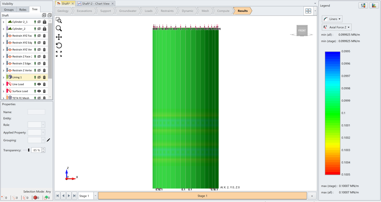
Figure 7. RS3 liners axial force results
The liner results for the axial force and hoop force in RS2 and RS3 are plotted in Figure 8 below.
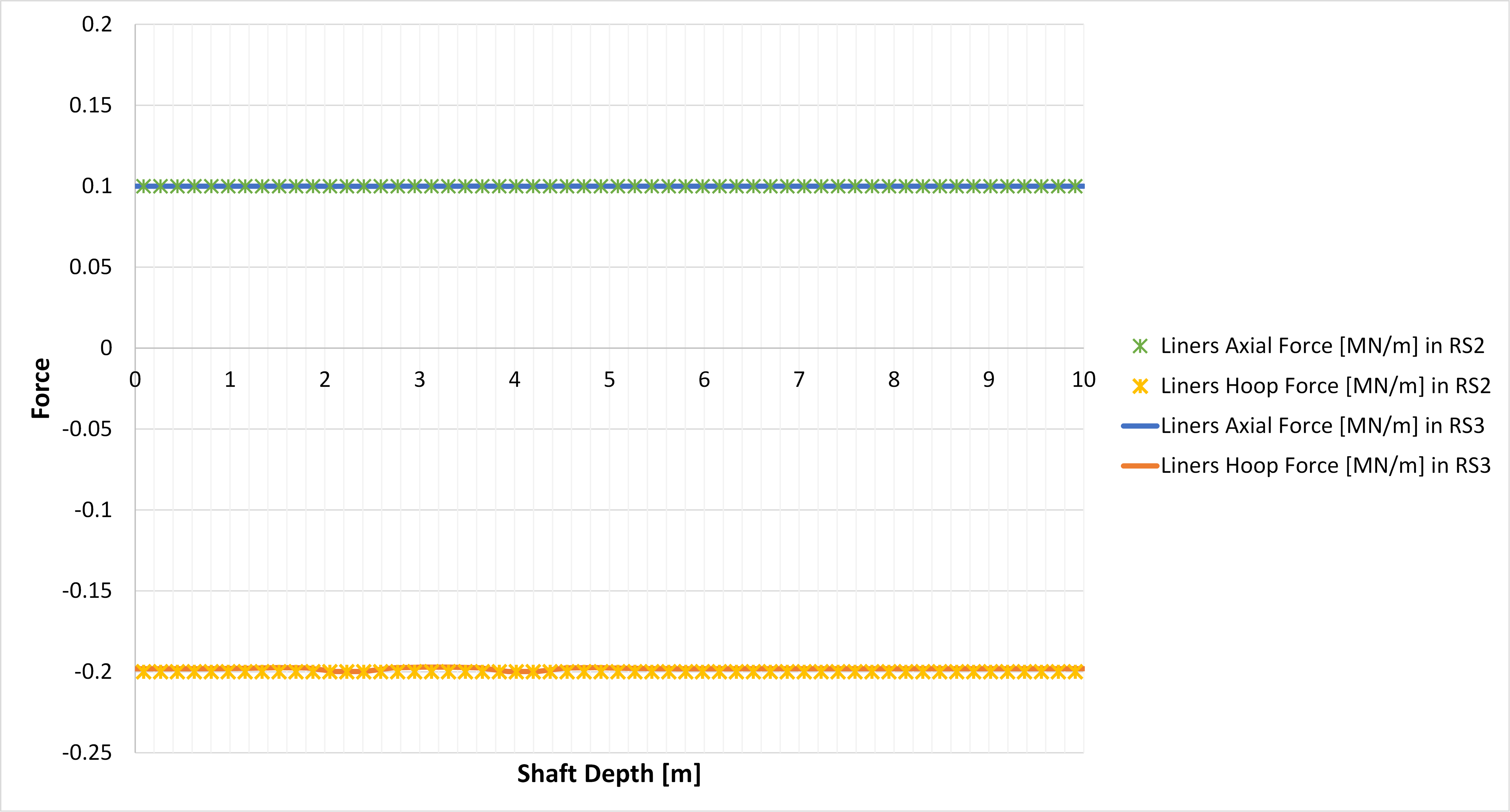
Figure 8. Liner results in RS2 and RS3
For more information, please see RS2 Knowledge Base for commonly asked tech-support questions about RS2 axisymmetric modelling. In the RS2 Knowledge Base page, select category = Axisymmetric Analysis in the dropdown menu.