Add Ponded Water Load
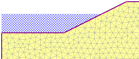
To define the distributed loading due to Ponded Water (e.g. impounded water against a slope or dam), a specialized option is provided, the Add Ponded Water Load option. This allows you to easily define hydrostatic loading due to Ponded Water by specifying total head boundary conditions on user-selected boundary segments.

Ponded water

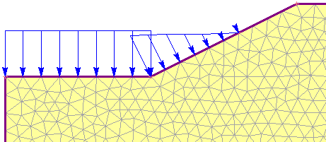
Weight of ponded water modeled as an equivalent distributed load
To use this option:
- Select Loading > Ponded Water Loads > Add Ponded Water Load
- You will see the Add Ponded Water Load dialog. In this dialog:
- Define the water level using one of the four methods provided in RS2:
- Total Head (m) – enter a value of Total Head. This value should be numerically equal to the y-coordinate of the water level you are modelling.
- Use Calculated Water Pressure – the positive calculated pore pressures on the boundary will be used to determine the water level.
- Apply using piezometric line – select a piezometric line to use.
- Apply using grid – select a water pressure grid to use.
- In a multi-stage model, the water level can be changed at different stages, by selecting the Stage Load check box (see below for details about staging).
- Define the water level using one of the four methods provided in RS2:
- select [OK] in the dialog, and you will be prompted to select the boundary line segment(s) on which to apply the load. In most cases you will be applying a Ponded Water load to segments of the External boundary.
- When finished selecting, press Enter or right-click and select Done Selection. The Ponded Water Load will be applied to all selected segment(s). RS2 will automatically create a series of distributed loads on the boundary which are equivalent to the hydrostatic force of the ponded water, as indicated by the display of blue arrows and the magnitudes.
Use Calculated Water Pressure
When the Use Calculated Water Pressure option is used, the load will be displayed with blue arrows with the label of “auto-calculated”. It will only be displayed on assigned stages.
Ponded Water Load Magnitude
When a Ponded Water Load has been added to a model, the load magnitude is defined in terms of the equivalent distributed load values (i.e. force per unit area), applied normal to the boundary. The values of the equivalent load magnitude are derived from:
- The value of water level (defined in the Add Ponded Water Load dialog)
- The elevation of each boundary vertex (relative to the water level)
- The value of the Pore Fluid Unit Weight entered in the Project Settings dialog.
After the analysis is computed, the Ponded Water Load magnitude will be displayed in the RS2 Interpret program. See the Ponded Water Result page for details.
Ponded Water Location
Here are some important points to remember when defining Ponded Water Loads.
Adding vertices at the water level
In order to precisely locate the intersection point of the water level with the model boundaries, you should add a vertex at the exact intersection point (i.e. at the y-coordinate corresponding to the Total Head value). This will ensure that the distributed load magnitude is correct (i.e. zero) at that location. If there is no vertex at the water level, then the magnitude and location of the load may be slightly incorrect at that point (i.e. the end of the load will correspond to the nearest mesh node, which may not be located at the water level).
Boundaries
In most cases you will be applying a Ponded Water load to segments of the External boundary. However, you can apply a Ponded Water load to Excavation, Material or Stage boundaries, if the material above the boundary has been excavated (i.e. the boundary represents the current ground surface). This allows you to model a surface excavation which is later filled with water.
Staging Ponded Water Loads
On a multi-stage model, Ponded Water loads can be staged by selecting the Stage Load check box in the Add Ponded Water Load dialog (Step 2b above). The staged value will depend on the water level method:
- Total Head: Select the Stage Total Head button. You will see the Stage Total Head dialog, in which you can enter a value of Total Head at each stage.
- Use Calculated Water Pressure: Select the Stage Application button. In the Stage Factor dialog, you can choose the stage(s) to apply the positive calculated pore pressure.
- Apply using piezometric line: Select the Stage Assignment button. In the Stage Assignment dialog, you can assign a piezo line to each desired stage(s). Click the Add button
 to add a stage.
 - Apply using grid: Select the Stage Assignment button. In the Stage Assignment dialog, you can assign a grid to each desired stage(s). Click the Add button
 to add a stage.
- If the model has only one stage, the Stage Load option will not appear in the Add Ponded Water Load dialog. This option is enabled when the model has multiple stages.
- If you are staging a Ponded Water Load, you should add a boundary vertex (as necessary) corresponding to EACH water level, so that the load is accurately applied to the correct boundary segments at each stage.
- If you are staging a Ponded Water Load, and the water level is being RAISED as staging progresses, then in Step 3 (above) you must remember to select ALL segments up to the MAXIMUM water level, so that the water level can rise to the desired level. (If you only select segments corresponding to the lowest water level, then the increasing load will only be applied on those segments).
Ponded Water Loads and Total Head Seepage Boundary Conditions
It is important to note that defining a Ponded Water Load does NOT define the Total Head conditions for a finite element groundwater seepage analysis. This must be done independently with the Set Boundary Conditions option in the Groundwater menu.
And conversely, defining the Total Head boundary conditions for a finite element seepage analysis, does NOT automatically define the loading due to the weight of the Ponded Water. The weight of the Ponded water can only be defined with the Add Ponded Water Load option, as described above.