Set Boundary Conditions
If the Thermal Method = Steady State FEA or Transient FEA in Project Settings menu, then the thermal boundary conditions are specified with the Set Thermal Boundary Conditions option in the Thermal menu.
To Set Thermal Boundary Conditions,
- Select the Thermal
 workflow tab
 - Select the Set Thermal Boundary Conditions
 option from the Thermal menu.
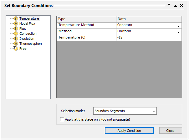
- In the Set Thermal Boundary Conditions dialog, choose the type:
- Temperature
- Nodal Flux
- Flux
- Convection
- Insulation
- Thermosyphon
- Free
Description of these types are explained in detail below.
For RS2 Thermal Boundary Conditions, when selecting multiple segments to apply a condition, the selected segments are being treated as one item. It means that the entire item needs to be edited or removed as a whole, making changes to a part of it is not permitted (e.g. the whole item will be removed if one segment is deleted).
Therefore, when assigning thermal boundary conditions to a group of segments, make sure the group can be treated as a whole, either until the boundary condition is removed or through the analysis.
See Section 2.7.3 in the Tutorial: Effects of thermosyphon on shallow foundation for an example application.
Edit Thermal Boundary Conditions
To edit existing thermal boundary conditions, you can select the thermal boundary condition item in the Visibility Tree. Then in the Properties section below the Model Items list, select Edit to edit thermal boundary condition in the popped-up dialog.
Thermal Boundary Condition Types
In RS2, thermal boundary condition types are divided into three categories: Stand Alone, Flexible, and Insulation.
- The Stand Alone category includes temperature and nodal flux boundary conditions. The boundary conditions of this category CANNOT be overlapped (only one boundary condition can bee applied at the location).
- The Flexible category includes flux, convection, and thermosyphon boundary conditions. The boundary conditions of this category CAN be overlapped (multiple boundary conditions can be applied to the same location).
- The Insulation category contains insulation boundary conditions, which are only applicable to joint elements.
- Free boundary condition is exclusive from any categories.
1. Temperature Boundary Condition
The Temperature Boundary Condition ![]() can be constant or time dependent. When temperature is constant, the apply method can be uniform, vertical incremental, horizontal incremental, or defined by initial and end values. For incremental methods, the initial temperature and the increment value should be defined. When temperature is time dependent, a temperature time function should be user-defined, and it is optional to include the N factor consideration (see the RS2 Thermal Analysis Theory Manual for more detail about N factor.)
can be constant or time dependent. When temperature is constant, the apply method can be uniform, vertical incremental, horizontal incremental, or defined by initial and end values. For incremental methods, the initial temperature and the increment value should be defined. When temperature is time dependent, a temperature time function should be user-defined, and it is optional to include the N factor consideration (see the RS2 Thermal Analysis Theory Manual for more detail about N factor.)
The Temperature Boundary Condition can be applied to material boundaries, joints, and structural interfaces.
2. Nodal Flux Boundary Condition
The Nodal Flux Boundary Condition ![]() can be constant or time dependent. For constant nodal flux, a flux value should be defined. For time dependent nodal flux, a nodal flux time function should be defined.
can be constant or time dependent. For constant nodal flux, a flux value should be defined. For time dependent nodal flux, a nodal flux time function should be defined.
3. Flux Boundary Condition
The Flux Boundary Condition ![]() can be constant or time dependent. For constant flux, a flux value should be defined. For time dependent flux, a flux time function should be defined. Other than tabular or sinusoidal, a flux time function can be defined using climate data which is based of ground surface energy balance.
can be constant or time dependent. For constant flux, a flux value should be defined. For time dependent flux, a flux time function should be defined. Other than tabular or sinusoidal, a flux time function can be defined using climate data which is based of ground surface energy balance.
4. Convection Boundary Condition
The Convection Boundary Condition ![]() applies to surfaces exposed to convective heat transfer. The temperature of the medium (denoted as a fluid), that transfers heat to boundary, can be specified as either a constant or a time dependent function. It is optional to define a working temperature range for a time dependent medium temperature. The heat coefficient is required too. In addition, if the convection boundary condition is applied to nodes, a perimeter can be specified.
applies to surfaces exposed to convective heat transfer. The temperature of the medium (denoted as a fluid), that transfers heat to boundary, can be specified as either a constant or a time dependent function. It is optional to define a working temperature range for a time dependent medium temperature. The heat coefficient is required too. In addition, if the convection boundary condition is applied to nodes, a perimeter can be specified.
5. Insulation Boundary Condition
Insulation Boundary Conditions ![]() are applied only to joint elements. It describes the thermal conductance between the joint and the body. Three options are provided: perfect insulate, none, and insulate. Perfect insulate means no heat transfer between surfaces, none means heat can freely pass through, and insulate means heat can transfer at a certain degree defined by an inputted conductivity value.
are applied only to joint elements. It describes the thermal conductance between the joint and the body. Three options are provided: perfect insulate, none, and insulate. Perfect insulate means no heat transfer between surfaces, none means heat can freely pass through, and insulate means heat can transfer at a certain degree defined by an inputted conductivity value.
6. Thermosyphon Boundary Condition
The Thermosyphon Boundary Condition ![]() is to model a thermosyphon system which can be used in arctic area to keep soils stay frozen. In RS2, the air temperature, delta temperature (ΔT ), and the max temperature need to be inputted. The heat transfer rate at a thermosyphon boundary can be determined with three methods: manual, arctic foundation, or Zarling and Haynes.
is to model a thermosyphon system which can be used in arctic area to keep soils stay frozen. In RS2, the air temperature, delta temperature (ΔT ), and the max temperature need to be inputted. The heat transfer rate at a thermosyphon boundary can be determined with three methods: manual, arctic foundation, or Zarling and Haynes.
7. Free Boundary Condition
A Free Boundary Condition ![]() represents no heat transfer over the boundary. It can be used to REMOVE existing boundary conditions in the model.
represents no heat transfer over the boundary. It can be used to REMOVE existing boundary conditions in the model.
Please specify the entity type (category) of the boundary condition you want to remove before applying a free boundary condition.
Thermal Time Dependent Functions
When a parameter for the thermal boundary condition is time dependent, a time dependent function should be inputted. Three types of time dependent functions are available: tabular, sinusoidal, and climate.
The tabular and sinusoidal types are available across all thermal boundary conditions. The climate type is available ONLY for the flux boundary condition. When using climate data to define a flux boundary condition, the heat flux for the ground surface is estimated based on the ground surface energy balance.
Selection Mode
Four selection modes are available to apply thermal boundary conditions: boundary segments, boundary vertices, boundary nodes, and all nodes.
All four selection modes are available for Temperature, Nodal Flux, Convection, Thermosyphon, and Free boundary conditions. For Flux Boundary Condition, it can only be applied to boundary segments. As for Insulation Boundary Condition, it can only be applied to JOINT boundary segments.
Thermal Boundary Conditions on Supports
In RS2, the Temperature Boundary Condition can be applied to joints and structural interface elements. The boundary condition can be assigned to both / + / - sides of the joint or structural interface. In addition, the Insulation Boundary Condition can be applied to both sides of joint elements.
Other thermal boundary conditions, or thermal boundary conditions on liners or bolts are not available.