Generalized Anisotropic
The Generalized Anisotropic Strength option allows you to create a composite material model in which you can assign any strength model in Slide2 to 1) any range of slice base orientations or 2) any set of anisotropic surfaces. For example, you could create a material with Hoek-Brown properties over a range of orientations or along a surface, and Mohr-Coulomb properties over another range of orientations or along a surface (e.g. to simulate a weak bedding orientation in a rock mass).
To define a Generalized Anisotropic Strength function set the Strength Type = Generalized Anisotropic in the Define Material Properties dialog. You will notice two Input Type options (or three if you have exported a Generalized Anisotropic model from Slide3), as explained below.
Input Type = Angle Range
This is the original Generalized Anisotropic function option. The user can input angle ranges and assign a material to each range.
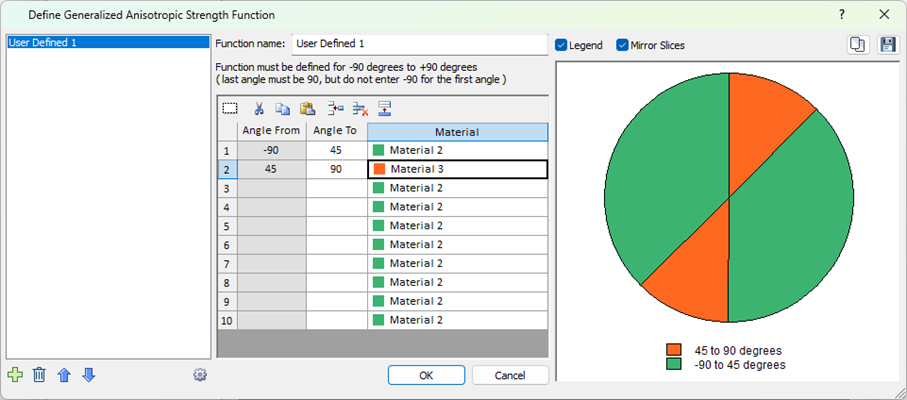
- The FIRST angular range always starts at –90 degrees (this is the default value of the FIRST Angle From value, and cannot be edited by the user).
- The angular ranges must be ordered counter-clockwise, from –90 to +90.
- The Angle From values cannot be edited, and are automatically defined by the Angle To value in the previous row.
- The LAST angular range always ends at +90 degrees (this must be entered by the user, as the LAST Angle To value).
- As the data is entered, the chart at the right of the dialog, will be updated to display the Generalized Anisotropic Function you are defining.
- Check the chart carefully, to make sure that you have defined the intended function (i.e. all angular ranges and materials are correct).
- In the case where you want to dictate whether the water parameters of the parent or child material are used, you can select the gear icon in the bottom left of the dialog to select to use the parent parameters. This setting affects water related parameters (piezolines, Hu value, alternate strength, pore pressure grids, Bbar, unsaturated strength, etc.) but not other components more involved with strength recalculation (rapid drawdown and multi-stage seismic settings). This is only available for the angle/range type. Older files before version 9.042 of Slide will have this setting off by default and files after this version will have this on by default.
Input Type = Angle or Surface
Two additional methods of defining anisotropy are found within this option. For users of Slide3, this option will be recognizable as the Generalized Anisotropic strength function in Slide3. The inputs are outlined below.
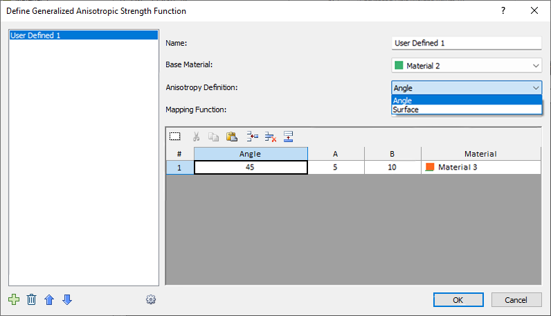
- Base Material: this represents the strength properties of the rock mass, for failure planes which are not within the defined orientation range of the anisotropic plane(s) or surface(s).
- Anisotropy Definition: This can be angle or surface. The two are outlined in detail further down.
- Mapping Function: defines how the strength is determined for each slice bottom. Can be A and B, Cosine, or Linear. More details further down.
Anisotropy Definition
Angle
This is similar to the Input Type = Angle Range option, but with a list of different mapping functions to choose from. As an example, we will explain the meaning of the previous image. In the function, the user has set the base material to Material 2, and defined an angle of 45 degrees for Material 3. This means that if the slice base falls along a 45 degree angle, the strength of Material 3 will be applied. If the slice base is orthogonal to this, the strength of Material 2 will be applied. What happens in the angle range in-between is defined by the Mapping Function selection (more details further down).
Surface
This option allows the user to define multiple anisotropic surfaces and assign different materials to each one. The point on the anisotropic surface that is closest to the given slice base is found, and the angle of the anisotropic surface at that point is taken as the angle of anisotropy for the given slice base. Once the angle is obtained, the calculations proceed as explained in the previous section.
The way the Anisotropic Surface works is explained in detail in the Anisotropic Linear Strength topic. Note that you must first use the Add Anisotropic Surface option to define an anisotropic surface before being able to access this option.
Mapping Function
A and B
A and B define discrete ranges over which the strengths of the different joints are applied or interpolated. As an example, we will refer back to the dialog image further up, and explain the meaning. In this case, Mapping Function is set to A and B.
In the function, the user has set the base material to Material 2, and defined an angle of 45 degrees for Material 3. This means that if the slice base falls along a 45 degree angle, the strength of Material 3 will be applied, otherwise the strength of Material 2 will be applied.
However, so as not to be so limited to the exact 45.0 degree angle, the A and B values are used to provide a range. The A value means that Material 3 will be applied within the range of [Angle +/- A], or [45 +/5]. The B value means that the strengths of the base material and Material 3 will be interpolated in the ranges [Angle + A, Angle + B] and [Angle - A, Angle - B], or [45+5, 45+10] and [45-5, 45-10]. In summary the above screenshot can be translated to this definition of anisotropy:
- Strength of Material 3 is applied for slice base in these angle ranges:
- [40, 50]
- Strength of Material 2 is applied for slice base in these angle ranges:
- [-90, 35]
- [55, 90]
- Interpolated strength of Material 2 and Material 3 is applied for slice base in these angle ranges:
- [50, 55]
- [35, 40]
A and B are explained in more detail in the Anisotropic Linear Strength topic.
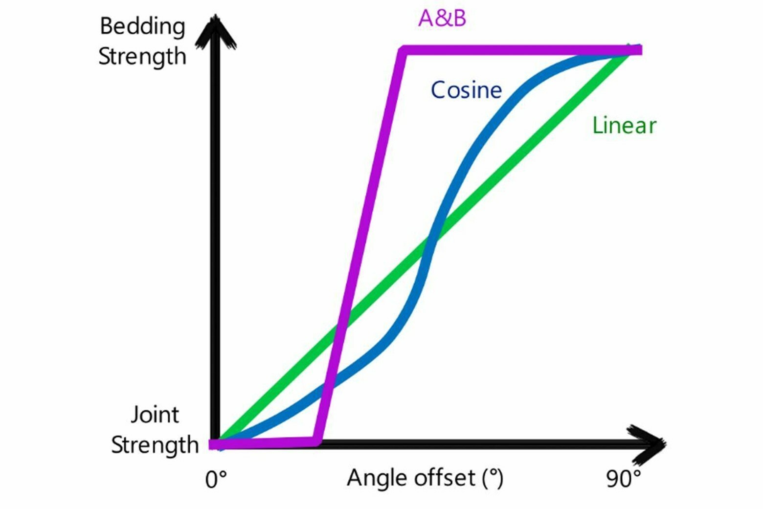
Cosine
Unlike the discrete ranges used in A and B, Cosine mapping function uses a continuous interpolation between the base and joint materials, based on the cosine of the angle offset angle (defined as the difference between the joint and angle and the slice base angle). If the cosine of the angle offset is 1, then the base strength is used. If the cosine of the angle offset is 0, then the joint strength is used.
Linear
Linear mapping function interpolates the strength linearly based on the angle offset. If the angle offset is zero, then the joint material is adopted, whereas if the angle offset is 90° (perpendicular to the joint direction), then the base material is adopted.
The three mapping functions are represented below:
- Worst Case: if more than one joint has been defined, the calculation for each joint is done separately, and the one which gives the lowest shear strength is adopted.
- Closest: the algorithm first determines which joint most closely aligned to the given slice base. Then the calculation proceeds as usual, only considering the nearest joint. Other joints are ignored.
- In addition, there is a checkbox where user can select what happens in case of a base material that is weaker than the joint material (whether the base or joint material strength should be used in the analysis).
- By default, the worst case joint is taken, and the base material is taken if it is weaker than the worst case joint.
Input Type = Imported from Slide3
The dialog of this option is very similar to the "Angle or surface, A, B" option, with the addition of one more option, 3D Anisotropy Handling:
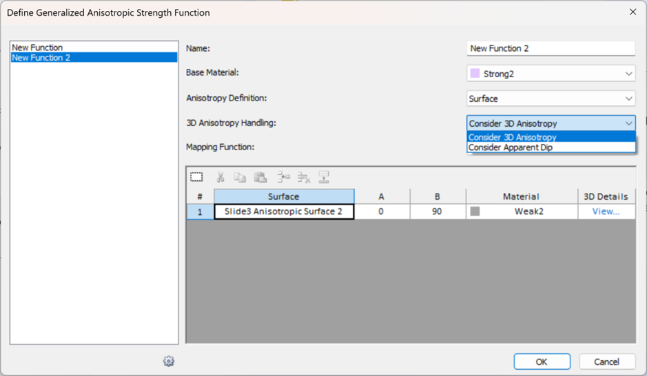
3D Anisotropy Handling = Consider 3D Anisotropy
This is the default. It means the 3D orientations of anisotropy are being considered in the analysis.
If Anisotropy Definition = Dip/Dip Direction, then the 3D dip and dip direction values will be considered in the analysis. To see the location of the 2D section relative to these dip/dip direction values, click the View option in the 3D Details column:
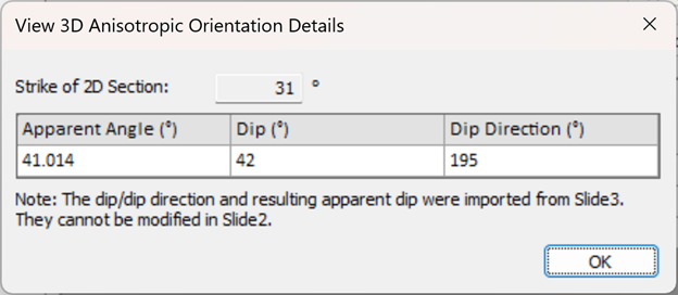
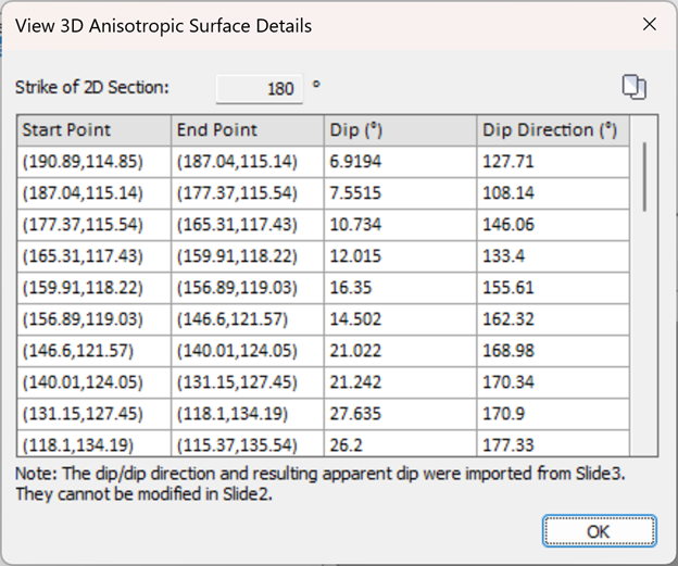
The strike of the 2D section as well as the Apparent Dip (the projected angle of anisotropy on the 2D section), are displayed here. If Anisotropy Definition = Surface, the dip and dip direction values along each segment of the Slide3 anisotropic surface will be considered in the analysis. To see these 3D details click the View option in the 3D Details column:
3D Anisotropy Handling = Consider Apparent Dip
Using this option will create a pure 2D analysis. The 3D orientations will not be considered in the analysis, as explained below:
- If Anisotropy Definition = Angle, only the apparent dip value will be considered as the anisotropic angle and the columns in the grid will only show that angle. Any 3D orientations will not be considered.
- If Anisotropy Definition = Surface, the "Imported from Slide3" anisotropic surface will be considered as a 2D anisotropic surface. Its corresponding 3D orientations will not be considered.
Notes
- The Dip, Dip Direction, A, B, values are the 3D values from the Slide3 model.
- If multiple 2D sections are exported from the Slide3 model, the 3D details will be different in each exported scenario.
- IMPORTANT: Using the A and B mapping function with narrow A and B values, while using the "Consider 3D Anisotropy" option may make it difficult for the slice bases on the 2D section to fall in the A and B ranges. In this case, the 2D section slice bases will fall in the rock mass orientations. For a proper results comparison, use Linear or Cosine mapping functions or keep a wide range in both the Slide3 and Slide2 model.
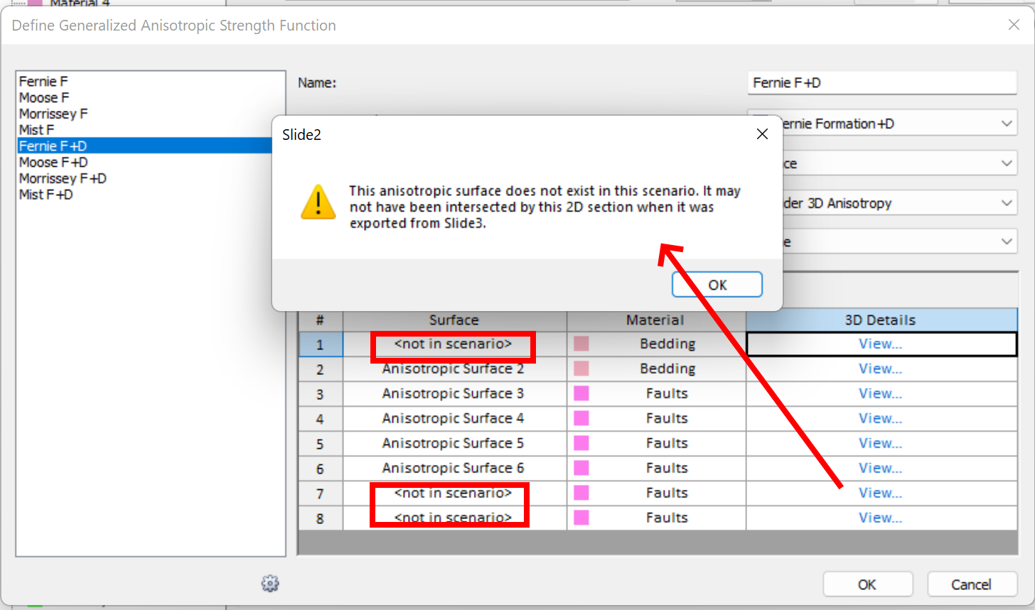
- In the case that the anisotropic surfaces assigned to a function do not intersect the Slide2 section, they will be displayed as follows in the
dialog. These "<not in scenario>" surfaces do not have an impact on the computations.
Additional Notes
A Generalized Anisotropic material (herein referred to as the "parent" material) can be defined to have differing base and joint material properties, which are herein referred to as "child" materials.
- The functions defined with each input type create two separate lists. For example you may have a list of two functions defined with Input Type = "Angle Range" which you can access from the dropdown when the Angle Range type is selected. You will see a different list and set of functions when the Input Type = Angle or Surface is selected.
- You cannot assign a Generalized Anisotropic function to itself.
- With Input Type = "Angle Range", no interpolation of material strengths occurs as does with the other Input Type on account of A and B. As a result, the water properties are used differently. Input Type = "Angle Range" uses the water properties of the child material that is used in the given angle range. Input Type = "Angle or Surface" uses the water properties of the parent material (the Generalized Anisotropic material itself)
- The unit weight of the parent material will be used to calculate the weight of a slice.
- The design factors specified in the Project Settings relating to material strength will be applied onto the child materials.
- Due to the algorithmic difference between the two Input Types, equivalent anisotropic definitions in the two types may exhibit a negligible numerical difference in FS.