Stage Liner Properties
The properties of a liner can be modified at different stages of a multi-stage model, by selecting the Stage Liner Properties checkbox under the Stage Properties section in the Define Liner Properties dialog. Any of the parameters entered in the Define Liner Properties dialog, can be increased or decreased by user-defined factors at different stages.
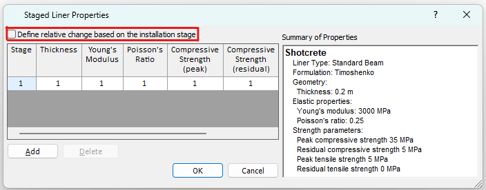
To apply stage factors, select the Define button beside Stage Factors option, you will be prompted to the Staged Liner Properties dialog.
Steps
Follow the steps to apply stage factors:
- Determine the staging method, whether it is based on the stage number, or liner installation stage. If it is the later one, select the Define relative change based on the installation stage option.
- In the Staged Liner Properties dialog, the parameters entered in the Define Liner Properties dialog are listed, with a default stage factor of 1.
- If the Define relative change based on the installation stage option is OFF, follow step 3a.
If the Define relative change based on the installation stage option is ON, follow step 3b.- Select the Add Stage button, until the number of rows in the dialog, is equal to the number of stages at which you need to modify the material properties.
- For example: If you need to modify material properties at 3 different stages, then select Add Stage TWICE, so that a total of 3 rows appears in the dialog.
- Select the Add Stage button to add the desired number of rows in the dialog. Define the stage number in each row.
- In each row, enter the required factor(s) which will be used to modify the indicated parameter(s). Note:
- The factors are multiplied by the parameter values in the Define Liner Properties dialog.
- For example: if you want to increase Young’s Modulus by 20%, enter a Factor of 1.2 for Young’s Modulus, at the desired stage(s)
- Leave the Factor = 1 for any parameter which does not change value
- A summary of liner property values and changes will be displayed at the right of the dialog.
- When finished, select OK to apply and exit the dialog.
Define Relative Change Based on the Installation Stage
In the Staged Liner Properties dialog, this option is provided to capture the material property change based on the installation stage.
By default, changes are applied relative to the absolute stage number. Alternatively, users can apply changes relative to the stage where liners are installed, by selecting the Define Relative Change Based on the Installation Stage option.
This option is designed mainly for the application of sequential tunnel excavation with liners. When Stage Factor option is ON, Define Relative Changes Based on the Installation Stage is OFF, the property changes with stage of ONE liner can be captured. However, if there are more than one liners of the same kind, each is installed at a DIFFERENT stage, then we need to define a liner for each installation. When Stage Factor option is ON, and Define Relative Changes Based on the Installation Stage is ON, the liner property changes with stage can be capture, even if liners are installed at different stages.
Note that the Define relative change based on the installation stage option will be in effect AFTER liners are installed in the model.
Example
To showcase how stage factors are applied to the model, an example is provided below.
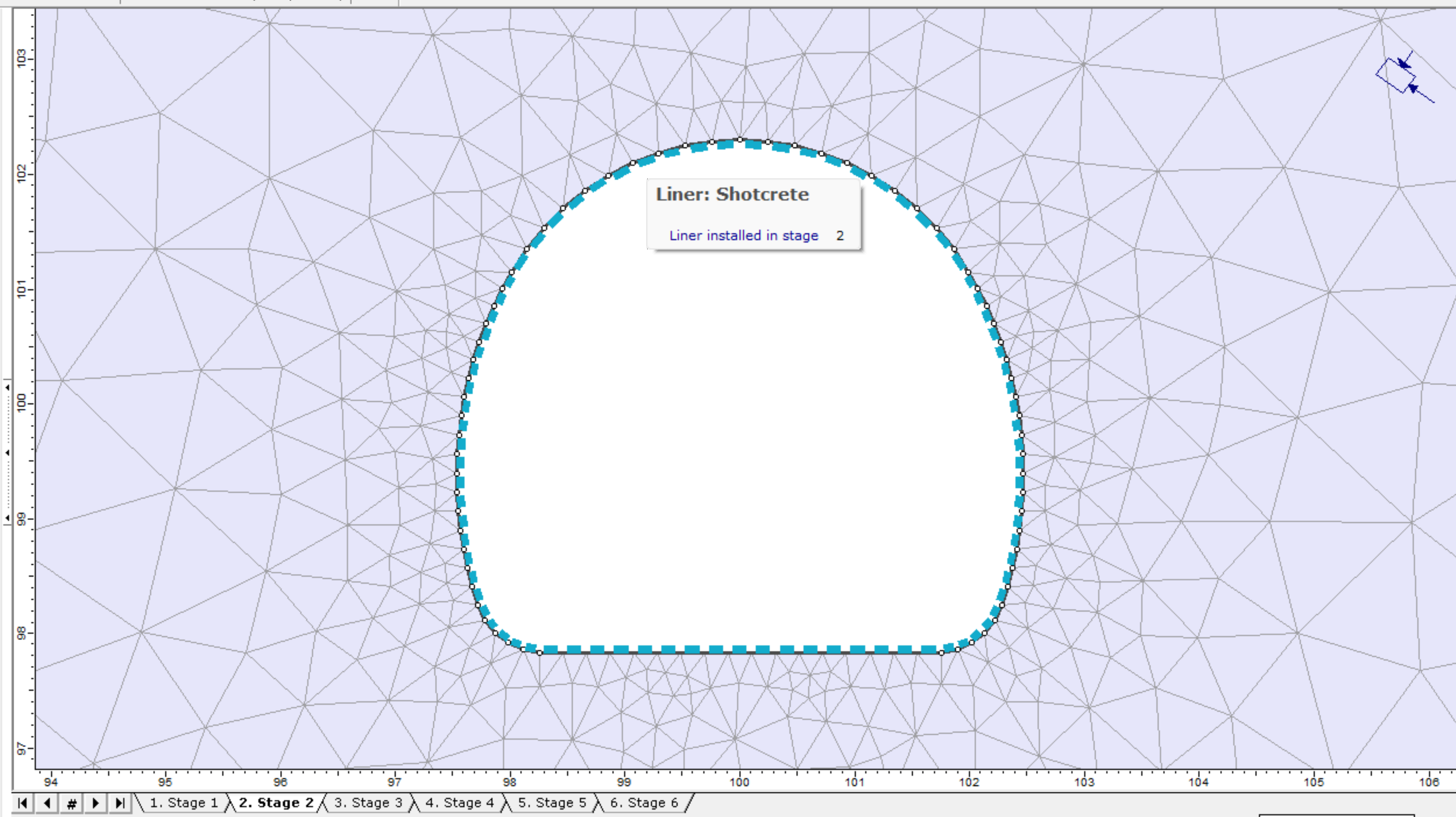
A liner is stalled from stage 2 (see figure below).
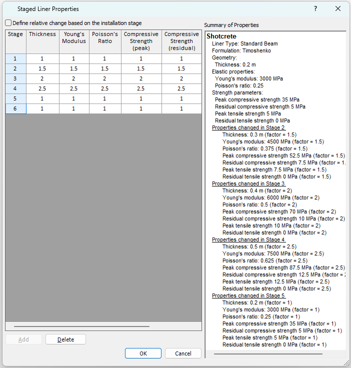
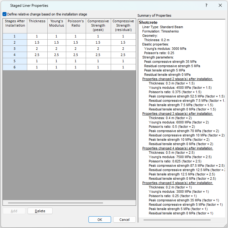
For Case 1, the Define relative change based on the installation stage option is off (see figure a). For Case 2, the Define relative change based on the installation stage option is on (see figure b). As seen in figure a and b, except for the option, input values are the same for both cases. The factors are applied to the model differently. For comparison, see below summary table.
When the option is selected, the first column will change from # of “Stage” to # of “Stages after Installation”.
 |  |
Absolute Stage Number |
x stage after installation |
Stage Factor |
|
When the option is OFF (case 1) |
When the option is ON (case 2) |
||
1 |
- |
1 |
1 |
2 |
0 |
1.5 |
1 |
3 |
1 |
2 |
1 |
4 |
2 |
2.5 |
1.5 |
5 |
3 |
1 |
2 |
6 |
4 |
1 |
2.5 |