Define Dynamic Load
Dynamic (time-dependent) loading on boundaries can be defined in terms of displacement, force, velocity or acceleration versus time. To define dynamic loads on boundaries:
- Select the Dynamic
 workflow tab.
 - Select Define Dynamic Loads from the toolbar or the Dynamic menu.
- You will see the Define Dynamic Loads dialog. To edit an existing load, click on the load name in the list at the left of the dialog. You can use the tools to Add
 , Delete
  , Copy
  a load or use Import button
  to import dynamic loads from a RS2 file.
 - You can rename the load or use the default name.
- Select the load Type. There are five possible dynamic load types:
- Line Force
- Distributed Force
- Displacement
- Velocity
- Acceleration
- Choose the load direction(s):
X and/or Y directions
- Normal (to boundary)
- To load a dynamic function file (.txt, .csv, .prn) to the grid, select the Load button
 . Select a file and click Open. A dialog will pop up for unit conversion as shown below.
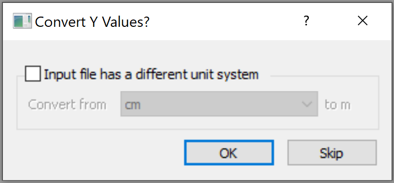
Select Skip in the dialog if the units in the data file are the same as the model.
This dialog is to align length and time units with the model units. If the file data uses a different unit system from the model, select the checkbox for Input file has a different unit system. Use the dropdown list to choose the unit system of the file data to perform conversion and select OK to apply.
You can perform a dynamic data analysis by clicking the Dynamic Data Analysis button
 in the dialog too. This option also available from Dynamic > Dynamic Data Analysis.
After defining dynamic loads, they can be applied to the model with the Add Dynamic Load option.
Drift Correction
The Drift Correction option is only applicable for Velocity or Acceleration load types. See the Dynamic Analysis Theory document for details.
Compliant Base
The Compliant Base option is only applicable for Velocity or Acceleration load types. Since a rigid base will null the effects of the absorb boundary conditions, in order to absorb outgoing waves from the model (to avoid the reflection of those waves back to the model), the motion restraint is transferred to stresses and applied to the boundaries.
Custom Bedrock
The Custom Bedrock option is only available when Compliant Base is selected. When enabled, you can define the bedrock properties, including the shear wave velocity, P wave velocity, and the rock unit weight. The velocities represent the speed of shear and compression waves propagate through the rock. Forces will be calculated based on Eq. (2.1) in the RS2 Dynamic Analysis Theory Manual.
The default values are Shear Wave Velocity = 1.5 km/s, P Wave Velocity = 3 km/s, and Rock Unit Weight = 0.027 MM/m^3.