Mesh Quality Overview
The options in the Mesh Quality sub-menu of the Mesh menu allow you to detect and troubleshoot problems which may exist with the finite element mesh. If you are experiencing problems with your analysis (e.g. non-convergence of solution, aborted computation, warning or error messages during compute, unusual analysis results), then it is advisable to check for mesh problems with the Mesh Quality options.
Overview
In a finite element mesh, it is generally desirable to avoid elements of high aspect ratio (i.e. long "thin" elements). The presence of such elements can have adverse effects on the analysis results.
- In general, such elements can influence analysis results, and lead to misleading and inaccurate results, which are dependent on the mesh.
- In extreme cases, such elements may even be responsible for non-convergence of the finite element solution, and the analysis will be aborted.
In order to help the user determine the "quality" of a finite element mesh, RS2 can automatically locate and highlight elements in a mesh, which are deemed to be of "poor" quality, according to user-definable criteria. This is done with the Show Mesh Quality and Define Mesh Quality options in the Mesh Qualitysub-menu.
Another problem which can occur, is that the mesh is composed of multiple disconnected regions (i.e. excavated areas create a discontinuous mesh). In general, this will lead to incorrect analysis results. The Contiguous Mesh Check option will check that the mesh is composed of one contiguous region, and if not will highlight the multiple regions and display a warning message. See the Contiguous Mesh Check topic for details.
Show Mesh Quality
In order to locate and highlight poor quality elements in a mesh, select the Show Mesh Quality ![]() option from the toolbar or the Mesh Quality sub-menu of the Mesh menu. If poor quality elements exist:
option from the toolbar or the Mesh Quality sub-menu of the Mesh menu. If poor quality elements exist:
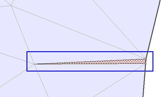
- All poor quality elements will be filled with a red hatch pattern.
- Since these elements will often be difficult to see, without zooming in to view, the general area(s) where poor quality elements have been found, will be additionally highlighted, by a blue rectangular box drawn around the regions of poor quality elements. This is shown in the figure below.
The elements which are highlighted, are those which conform to the criteria of a "poor quality" element, as defined in the Define Mesh Quality dialog. In most cases, you will need to zoom in to get a good view of the highlighted poor quality elements, and determine what may be the cause of the problem.
Poor quality sliver element detected by mesh quality check

NOTE: after you generate the mesh for a RS2 model, it is always a good idea to use the Show Mesh Quality option to see if there are any problems with your mesh.
Define Mesh Quality
The Define Mesh Quality dialog allows you to specify the criteria which define a "poor quality" element. There are three criteria which may be specified:
- ratio of (maximum side length) / (minimum side length)
- Minimum interior angle
- Maximum interior angle
The default values for the above criteria, are 30, 2 degrees and 175 degrees, respectively. An element will be determined as "poor quality", if ANY of these three criteria are met. You may change the current values for these criteria, or change the default values by selecting the Defaults button.
Note that these three criteria are not independent. The primary criterion is the minimum interior angle, since a sliver element will always have at least one small interior angle, but not necessarily a high side length ratio or large maximum interior angle.
Mesh Quality Statistics
Statistics for poor quality elements can be viewed by selecting the link in the Define Mesh Quality dialog. This will display the number of poor quality elements for each of the three criteria, and the total number of poor quality elements. These statistics are also listed in the Report Generator.
Reasons for poor quality mesh elements
There are various reasons why poor quality mesh elements may be generated. Typically the problems are due to:
- Vertices which are very close to each other.
- Poorly graded discretization of model boundaries (for example, a finely discretized boundary immediately adjacent to, or close to, a coarsely discretized boundary, will often result in a poor quality mesh).
- The geometry of your model boundaries, for example, the relative distances between boundaries, or the way in which they intersect (e.g. nearly parallel boundaries which intersect at a very small angle).
Fixing a poor quality mesh
- If the problem is vertices which are very close to each other, then you may need to delete unnecessary vertices, or move vertices, so that they are further apart, or exactly coincident. If vertices were intentionally located very near to each other, and this is causing a problem, then you may want to consider modifying your geometry slightly, so that poor quality elements are not generated.
- If a poor discretization is responsible for the poor mesh, then you will need to modify the discretization of the appropriate boundaries. This may involve use of the Custom Discretize option, the Advanced Mesh Regions option in the Mesh Setup dialog, or the Increase Discretization Density option.
- If the actual model geometry is responsible (e.g. very thin material layers), then various solutions might be appropriate, involving Custom Discretize, or modifying the boundaries slightly, so that the problem does not occur.
NOTE: the Geometry Cleanup option will automatically merge vertices which are very close to each other according to a user-defined tolerance. See the Geometry Cleanup topic for details.