Generalized Anisotropic
The Generalized Anisotropic Strength model allows you to define Anisotropic strength properties for a material using any combination of failure criteria applied over user-defined orientations. There are two methods of defining the anisotropy:
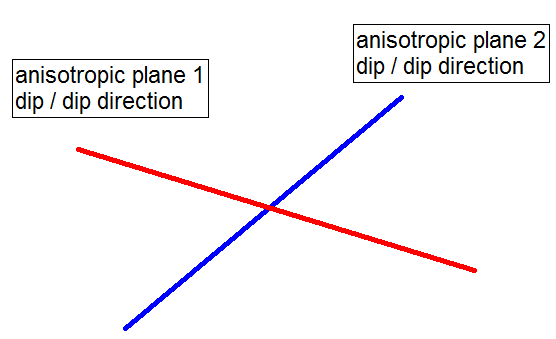
- Dip/Dip Direction - you can define one or more planes of anisotropy, with 3-dimensional orientation defined by Dip and Dip Direction, OR
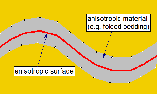
- Surface - you can define a general 3D anisotropic surface (e.g. to follow the orientation of folded bedding strata).
Each anisotropic plane or surface can be assigned its own failure criterion, within a specified angular range. The rock mass is also assigned a failure criterion. The strength of any failure plane through the anisotropic material can then be calculated, using an interpolation method, as described below.
To define a Generalized Anisotropic Strength Function:
- Set the Failure Criterion = Generalized Anisotropic in the Material Properties dialog.
- Select the Edit
 button beside the failure criterion combo box.
 - You will see the Define Generalized Strength Function dialog.
- To edit an existing Generalized Anisotropic Strength function, select the Function Name from the list at the left of the dialog.
- To create a new Generalized Anisotropic Strength function, select the Add
 button at the lower left corner of the dialog, and enter a Function Name.
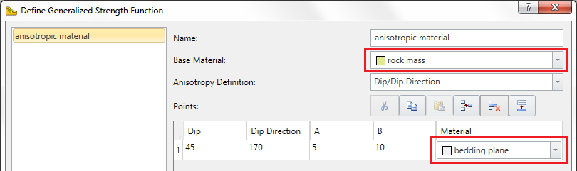
- Select the Base Material for the function. This will represent the strength properties of the rock mass, for failure planes which are not within the defined orientation range of the anisotropic plane(s) or surface.
- Select the Anisotropy Definition - Dip/Dip Direction or Surface. For each plane or surface, assign a material and enter the required parameters as described below.
- Select a Mapping Function - A and B, Cosine, or Linear. These options are described further down.
- When all data has been entered, select OK, and you will be returned to the Material Properties dialog. The name of the function you have just defined will appear in the Generalized Function list. By selecting a Function Name from this list, you can now apply a Generalized Anisotropic Function to any material in the model.
Anisotropy Definition - Dip/Dip Direction
The Anisotropy Definition = Dip/Dip Direction option allows you to define one or more planes of anisotropy, with orientation defined by Dip and Dip Direction.
- By default, one anisotropic plane will be defined. Enter the Dip and Dip Direction of the anisotropic plane, and select a Material for the anisotropic plane.
- If you have more than one anisotropic plane, select the Insert Row
 button to add the required number of rows. Enter the Dip and Dip Direction.
Definition of Dip / Dip Direction
The definition of Dip and Dip Direction follows the standard convention:
- Dip Direction is measured from North, with clockwise positive convention.
- Dip is measured from the horizontal, with downward positive convention.
Anisotropy Definition - Surface
The Anisotropy Definition = Surface option allows you to assign a surface which corresponds to the mean orientation of a non-planar anisotropic region. For example as illustrated in the figure below. For simplicity this is illustrated in 2D however the actual surface is 3-dimensional.
In order to use this option:
- you must first define the Anisotropic Surface using the Anisotropic surface option in the Surfaces menu.
- you will then be able to assign this surface to the Generalized Anisotropic material.
The Anisotropic Surface option is useful because it allows you to assign a single anisotropic material type, to a non-planar material zone with variable anisotropic orientation. The determination of shear strength is exactly the same as described above for the planar Dip/Dip Direction option, with the following additional step:
- For a given column base, the NEAREST point on the Anisotropic Surface is first determined.
- This gives a local value for the Dip/Dip Direction of the anisotropic surface.
- The angle between the column base plane and the local anisotropic surface orientation is determined.
- The calculation of shear strength for the column base, then proceeds as described above for the planar Dip/Dip Direction option.
Mapping Function
A and B
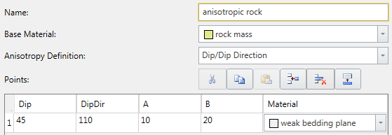
A and B define discrete ranges over which the strengths of the different joints are applied or interpolated. Let's assume a rock mass has a single well defined plane of anisotropy, such as a bedding plane, with the following inputs:
- Name = anisotropic rock
- Base Material = rock mass
- Anisotropy Definition = Dip/DipDirection
- Only one anisotropic plane is defined
- Dip = 45 (dip of anisotropic plane in degrees)
- Dip Direction (DipDir) = 110 (same as the Dip Direction of the slope in degrees)
- A parameter = 10
- B parameter = 20
- Material = weak bedding plane
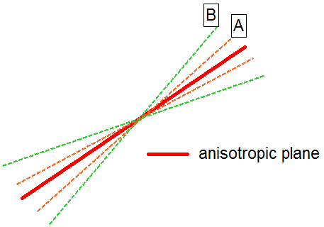
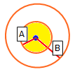
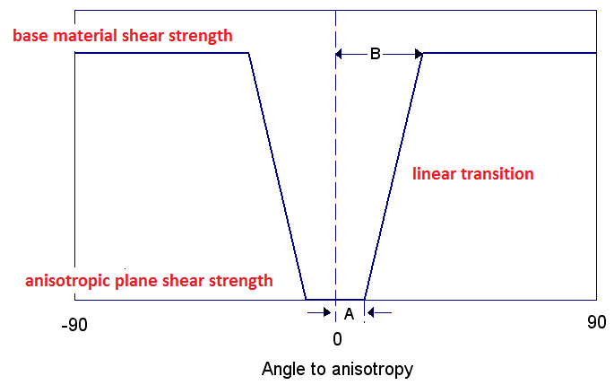
A 2D representation of the A and B parameters is shown below. If a shear plane (column base) lies within the A angle, the anisotropic plane strength is applied. If a shear plane lies outside of the B angle, the rock mass strength is applied. If a shear plane lies between the A and B angles, a linear transition between the rock mass strength and the anisotropic plane strength is applied.
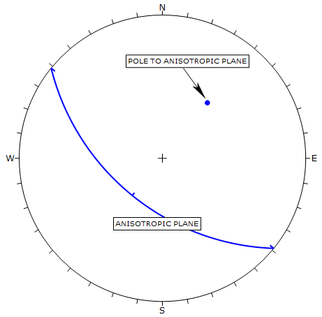
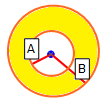
The best way to illustrate the definition of the A and B parameters is with the aid of a stereonet. The 3-dimensional orientation of an anisotropic plane is given by entering the Dip and Dip Direction of the plane. On a stereonet, a plane can be represented as a great circle with corresponding pole (normal vector) as shown below.
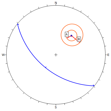
The A and B parameters define the angular radius of two cones centered on the pole vector of the anisotropic plane, as shown in the following figure.
The A and B mapping function is applied as follows. For a given column in a sliding mass, the orientation (dip and dip direction) of the base of the column is determined. The normal vector to the base of the column is then determined.
- If the normal vector of the column base is WITHIN radius A of the normal vector of the anisotropic plane, then the strength model selected for the Anisotropic Plane is applied (in the above example the "weak bedding plane" material).
- If the normal vector of the column base is OUTSIDE radius B of the normal vector of the anisotropic plane, then the strength model selected for the Base Material is applied (in the above example the "rock mass" material).
- If the normal vector of the column base is OUTSIDE radius A and WITHIN radius B, then the strength applied is based on a linear transition between the Anisotropic Plane strength and the Base Material strength, as shown in the figure below.
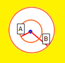
The following figure illustrates how the shear strength is derived using the A and B mapping function. Within angular radius A the shear strength of the anisotropic plane is applied. Outside of angular radius B the base material (rock mass) strength is applied. For angles between A and B the transition of shear strength is assumed to be linear.
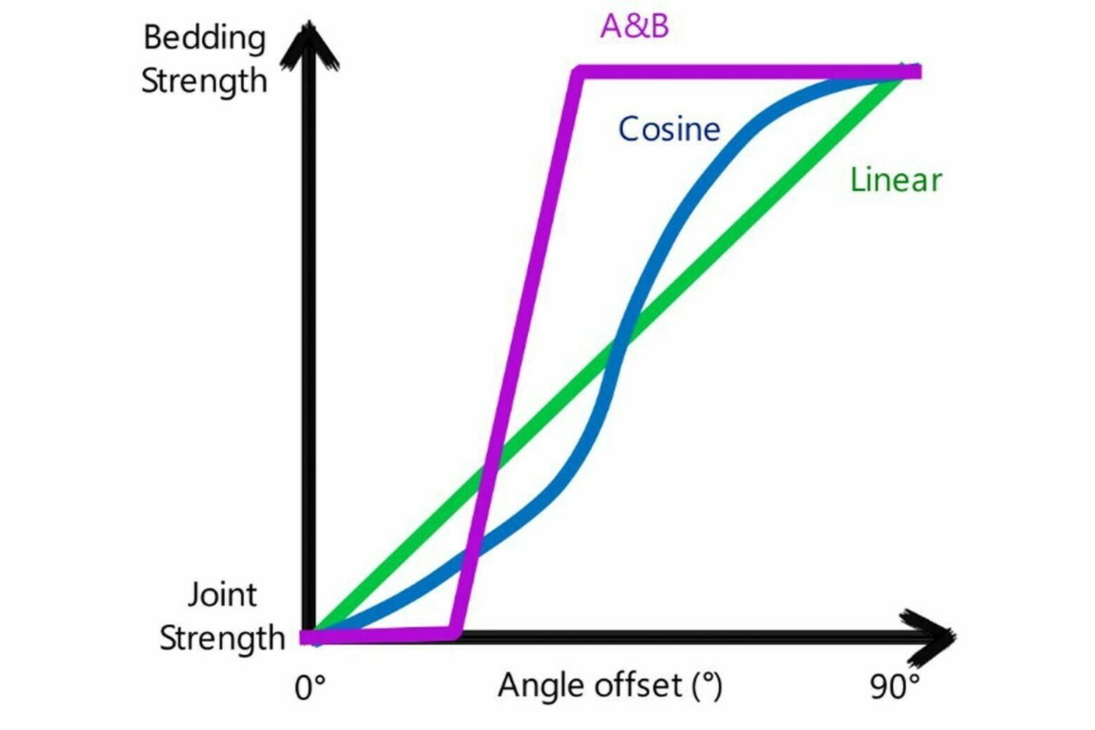
Cosine
Unlike the discrete ranges used in A and B, Cosine mapping function uses a continuous interpolation between the base and joint materials, based on the cosine of the angle offset angle (defined as the difference between the joint and angle and the slice base angle). If the cosine of the angle offset is 1, then the base strength is used. If the cosine of the angle offset is 0, then the joint strength is used.
Linear
Linear mapping function interpolates the strength linearly based on the angle offset. If the angle offset is zero, then the joint material is adopted, whereas if the angle offset is 90° (perpendicular to the joint direction), then the base material is adopted.
The three mapping functions are represented below:
A and B define discrete ranges over which the strengths of the different joints are applied or interpolated. Let's assume a rock mass has a single well defined plane of anisotropy, such as a bedding plane, with the following inputs:
Multiple Anisotropic Planes
In the case of multiple joints, you can click on the gear icon in the bottom left of the dialog to determine how you want them to be treated:
Worst Case: if more than one joint has been defined, the calculation for each joint is done separately, and the one which gives the lowest shear strength is adopted.
Closest: the algorithm first determines which joint most closely aligned to the given slice base. Then the calculation proceeds as usual, only considering the nearest joint. Other joints are ignored.
In addition, there is a checkbox where user can select what happens in case of a base material that is weaker than the joint material (whether the base or joint material strength should be used in the analysis).
By default, the worst case joint is taken, and the base material is taken if it is weaker than the worst case joint.
Generalized Anisotropic Material Assignments
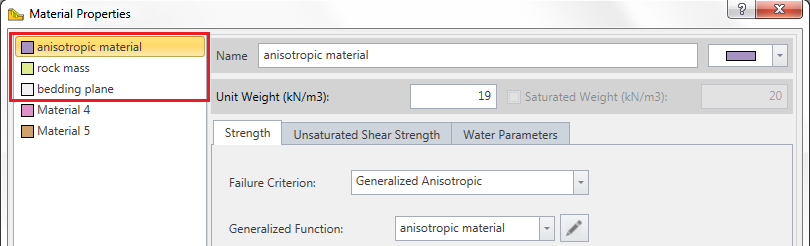
A Generalized Anisotropic material in Slide3 will always require at least three material assignments:
- One material for the Generalized Anisotropic material.
- One material for the rock mass strength assignment.
- One material for the anisotropic plane or surface strength assignment.
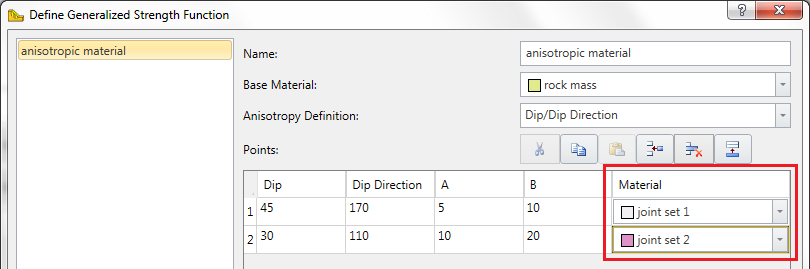
The Generalized Anisotropic material is really a composite material with a rock mass strength component and one (or more) anisotropic strength component(s). If the Anisotropy definition = Dip/Dip Direction, and more than one anisotropic plane is defined, then each plane may have a different material assigned. This is illustrated below.
Failure Criteria for Base Material and Anisotropic Planes
You may use any material strength model for the base material (rock mass) and anisotropic planes. For example, you might use:
- Generalized Hoek-Brown (for the rock mass)
- Barton-Bandis (for anisotropic planes or surface)
You are not limited to the Mohr-Coulomb strength model when using the Generalized Anisotropic material option in Slide3.
Tensile Strength
Please refer to the Tensile Strength page for more information.
Generalized Anisotropy - Surface
Additional Notes
A Generalized Anisotropic material (herein referred to as the "parent" material) can be defined to have differing base and joint material properties, which are herein referred to as "child" materials.
- You cannot assign a Generalized Anisotropic function as a child material.
- The water properties of the parent material will be used for the Generalized Anisotropic material. The water properties of the child material are ignored.
- The unit weight of the parent material will be used to calculate the weight of a column.
- The design factors specified in the Project Settings relating to material strength will be applied onto the child materials.