Add Triangular Load
The Add Triangular Load option allows you to define a distributed load which varies linearly between two points along a boundary. The load can be triangular (zero at one end) or trapezoidal (different non-zero values at each end).
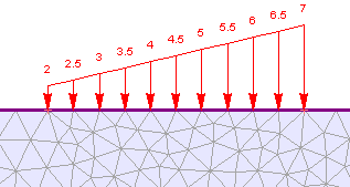
Trapezoidal distributed load
Triangular load can be defined in two different methods: Linear and Elevation.
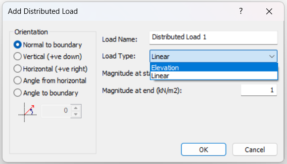
Linear Triangular Load
A linear triangular load method requires magnitude specifications at the start point and the end point the linear gradient is automatically handled. Subsequently, the two points need to be sequentially selected from the viewport. To apply a triangular or trapezoidal distributed load:Add Triangular Load
- Select Add Triangular Load
 from the toolbar or the Distributed Loads sub-menu of the Loading menu.
 - Select the load orientation and enter the load magnitudes (two magnitudes are required, for the start and end points of the load)
- For multi-stage models, you can stage distributed loads by selecting the Stage Load check box and entering a factor for the load magnitudes at each stage. If the load is not staged, it is applied with the same magnitude at all stages.
select [OK] in the dialog. Now you must graphically select the start and end points of the load, as described below.
NOTE: For meshed models, the start and end points must be on boundary vertices to preserve the mesh. Otherwise, RS2 prompts to remove the mesh to add the load as defined. For unmeshed models, the points can be anywhere along the boundary.
- Click the start vertex of the load on the boundary.
- Move the cursor along the required boundary. As the cursor tracks the boundary, the load distribution preview is rendered along the path and the load preview is displayed. Note the following:
- A triangular load may span multiple segments on the same boundary.
- A triangular load can be applied only along a single boundary. For loads extending across connected boundaries, define separate triangular loads for each boundary segment.
- Flip Angle: If the load direction is opposite to the required direction, use the Flip Angle option to reverse it. Right-click and select Flip Angle from the shortcut menu, or type f in the prompt line and press Enter.
- When the cursor reaches the required end vertex, click to add the load to the model.
Elevation Triangular Load
The Elevation Load type allows users to apply a distributed load whose magnitude varies linearly with elevation. It is intended for cases where pressure increases or decreases with vertical position, such as depth-dependent loading. The load is defined relative to the highest elevation along the selected application surface.
Two values define the elevation-based load distribution: Magnitude at Highest Elevation and Load Gradient.
- Magnitude at Highest Elevation: The load magnitude at the highest point along the applied surface.
- Load Gradient: The rate at which the load changes per unit vertical distance in the negative vertical direction.
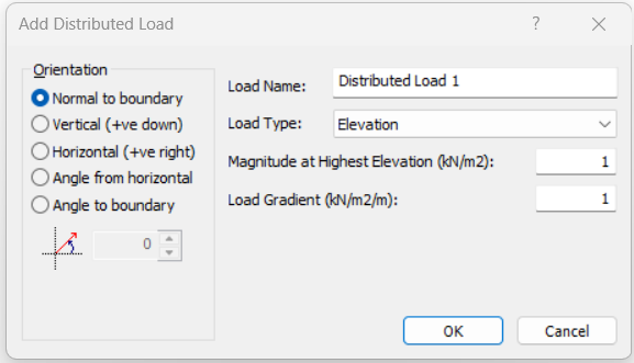
For horizontal surfaces, the elevation does not change, so the load magnitude remains constant along the surface. For inclined or vertically varying surfaces, the load changes linearly based on the change in elevation from the highest point.
The procedure to add the Elevation load is identical to that of Linear load.
At any point on the applied surface, the load magnitude is calculated from the highest elevation using the specified load gradient.
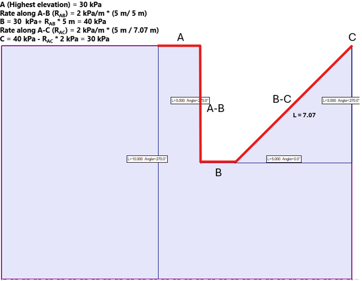
Load at point = Magnitude at Highest Elevation + Load Gradient × Vertical depth below highest elevation
When the surface is inclined, the equivalent rate of change along the length of the applied surface depends on the vertical elevation change over that length:
Rate of change along surface = Load Gradient × (Total increase in depth ÷ Surface length)
Below shows an example calculation when the Magnitude at the Highest Elevation is set to be 30 kPa and the Load Gradient = 2 kPa/m
Load Magnitude, Orientation and Staging
For details about defining the load magnitude, orientation and staging, see the Add Uniform Load topic, as the same information applies to both Uniform and Triangular distributed loads.
NOTE: for a Triangular load, if you are staging the load magnitude, you may define different stage factors at each end of the load by selecting the Different stage factors on each end check box in the Stage Factors dialog.