Setup
The first section in the Baecher DFN Wizard is the Setup. This section defines the name of the DFN and the 3D bounding box of the DFN. The fractures will be generated in this box. The 3D bounding box is shown in the Rock Mass viewport.
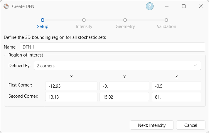
If Linear or Borehole traverses (e.g., Linear Scanline, Linear Borehole Oriented Core, Linear Borehole Televiewer, Curved Borehole Oriented Core, Curved Borehole Televiewer) are defined in the Pole Data Grid, then the default bounding box will encompass all the pole planes along those traverses. If no Linear or Borehole traverses are defined in the Pole Data Grid, then the default bounding box dimension is 20 m x 20 m x 20 m with a centre coordinate of (0, 0, 0).
If part of a generated joint falls outside the bounding box, its centre will be shifted so that the entire joint area falls inside the bounding box.
It is recommended to define a bounding box larger than the area that is being modelled to avoid boundary effects.