Interface and Joint Connectivity at Intersections
When joints intersect composite liners, the connectivity of the joint, interface, and liner elements must be considered carefully. RS3 maintains separate nodes where necessary to allow relative movement across a joint or interface, while retaining shared nodes where structural continuity of the liner is required.test
The following examples illustrate the node-splitting and connectivity rules used by RS3 for joints intersecting composite liners.
Node Splitting Along a Joint
A joint is modelled as a zero-thickness element between two solid regions. During mesh generation, each node along the joint surface is duplicated. The two nodes in each pair have identical coordinates, but each belongs to a different solid face.
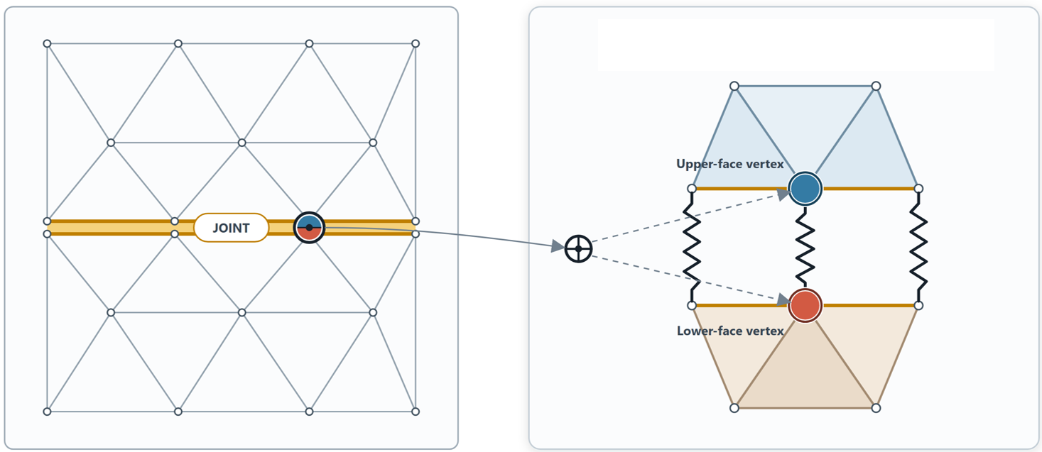
The upper node is connected only to the solid elements above the joint, while the lower node is connected only to those below the joint. The two nodes are coupled through the joint element, represented schematically by a spring between the coincident nodes. The spring represents the normal and shear stiffness of the joint. Because the two faces share coordinates but do not share a node, the solid regions on either side of the joint can open, close, or slide relative to each other, according to the joint slip criteria
Two Joints Intersecting
When two joints fully cross, the same node-splitting rule is applied independently to both joints. Away from the intersection, each joint produces a pair of coincident nodes, with each node connected to the solid region on its respective side of the joint.
At the intersection, both joints split the same location. Consequently, the mesh contains four coincident nodes, with each node associated with one of the four surrounding quadrants. Nodes at different quadrants are therefore connected only to the solid elements within their respective quadrants.
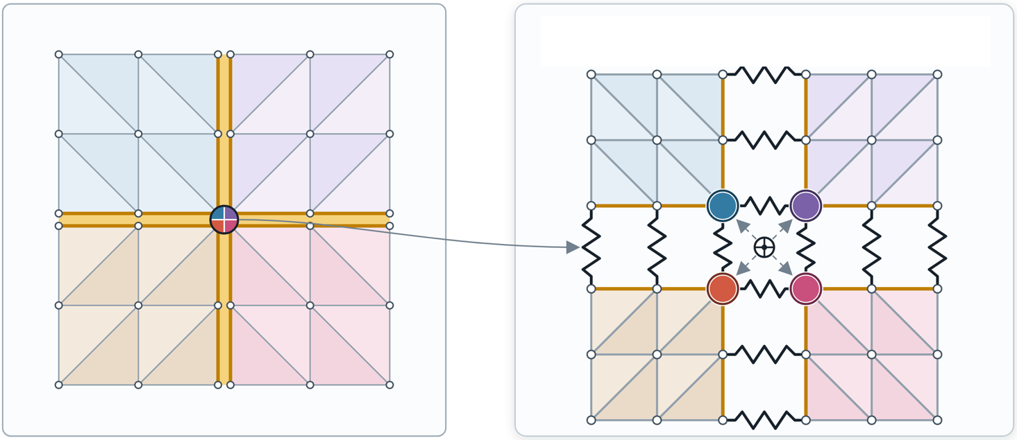
In the figure above, the four solid regions are separated visually so that the individual nodes can be distinguished. Joint springs connect adjacent node pairs across each joint: two across the horizontal joint and two across the vertical joint. No single node is shared by more than one quadrant. This connectivity allows opening, closing, and sliding to occur independently across either joint while the four nodes remain coincident in the assembled mesh.
A Joint Meeting an Interface of a Composite Liner
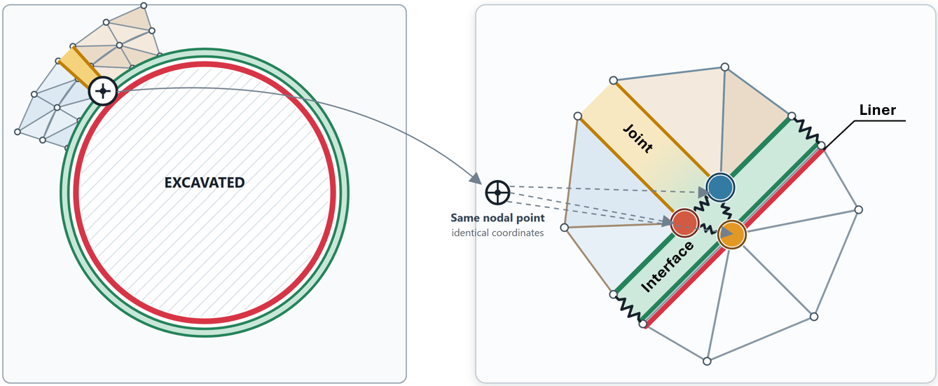
When a joint terminates at an interface between the rock and a liner, the node at the intersection is split on the rock side of the interface. The two rock-side nodes (red and blue) are coincident but belong to the two sides of the joint. The joint element connects these two nodes, while the interface elements connect the split rock-side nodes to the liner node.
This connectivity allows the rock to open or slide along the joint while maintaining a single liner node at the intersection. The liner therefore remains structurally continuous through the joint–liner intersection.
Joint Crossing a Liner with Interfaces on Both Sides
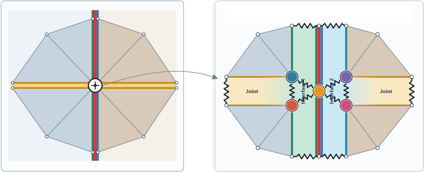
Consider a sheet pile or diaphragm wall, represented by a composite liner with an Interface–Liner–Interface configuration. When a joint crosses the composite liner, the joint terminates at each interface. At each side of the liner, the rock-side node is split to accommodate the joint. This produces two split nodes on each side of the liner: the blue and red nodes on one side, and the purple and magenta nodes on the other.
The split rock-side nodes are connected to the corresponding liner node through interface elements. The joint elements connect the appropriate pairs of split nodes across the joint. The liner nodes themselves remain continuous through the intersection.
Thus, the joint can open or slide on either side of the wall without introducing a discontinuity into the structural liner. The interfaces continue to provide the appropriate interaction between the rock and the liner along the remainder of the wall.
T-Junction of Two Composite Liners
T-junctions and L-junctions are common when modelling the base slab of a deep excavation, a tunnel intersecting a shaft, intersecting tunnels, or retaining-wall systems. When these configurations are modelled using composite liners, the arrangement of the liner and interface layers controls not only the interaction between the ground and the support, but also the connectivity between intersecting liner elements.
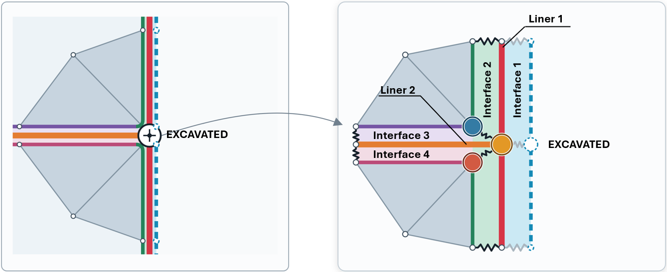
The figure above shows a plan view of two composite liners with an Interface–Liner–Interface configuration meeting at a T-junction. The right-hand side of Liner 1 is excavated, so the corresponding interface (interface 1) is removed. Liner 2 terminates against the left-hand side of Liner 1, where Interface 2 provides the connection between Liner 1 and the surrounding ground. At the intersection, Interfaces 3 and 4 terminate at Interface 2. These interfaces form L-shaped connections with the composite liner. The corresponding rock-side nodes are connected to the shared liner node through interface elements, allowing the two liner systems to remain connected at the T-junction.
The connection between Liner 1 and Liner 2 cannot be established correctly if Interface 3 is omitted from Liner 2. The figure below illustrates the effect of omitting one of the interfaces at a T-junction. Although the liner elements may appear geometrically coincident, the required interface connectivity is not established.
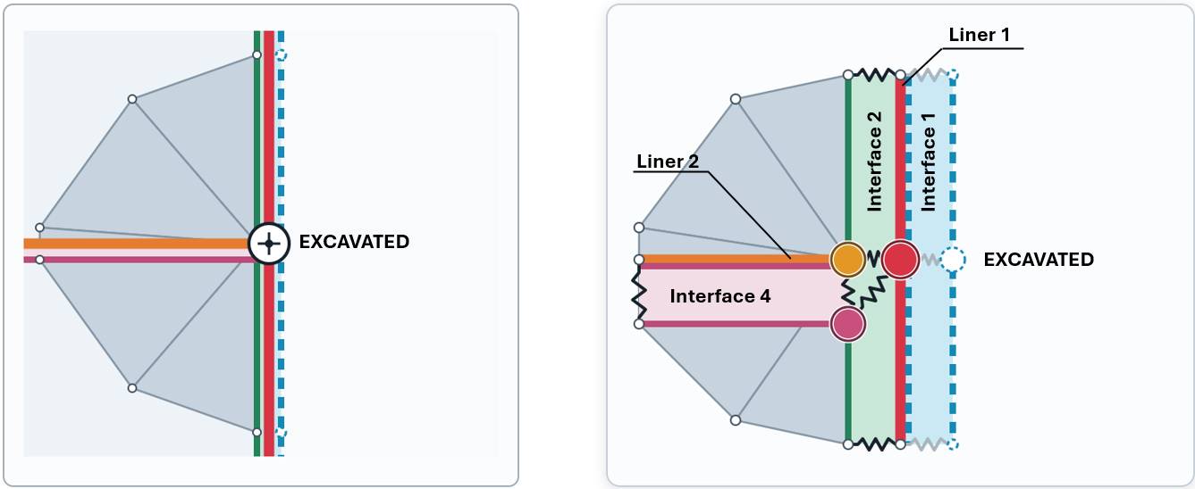
In this case, the Liner 1 remains continuous, but Liner 2 terminates at a separate node that has the same coordinates as the junction node. Because the nodes are not connected through the required interface elements, Liner 2 is disconnected from the Liner 1.
Corner Excavation: Top-Left Quadrant Removed
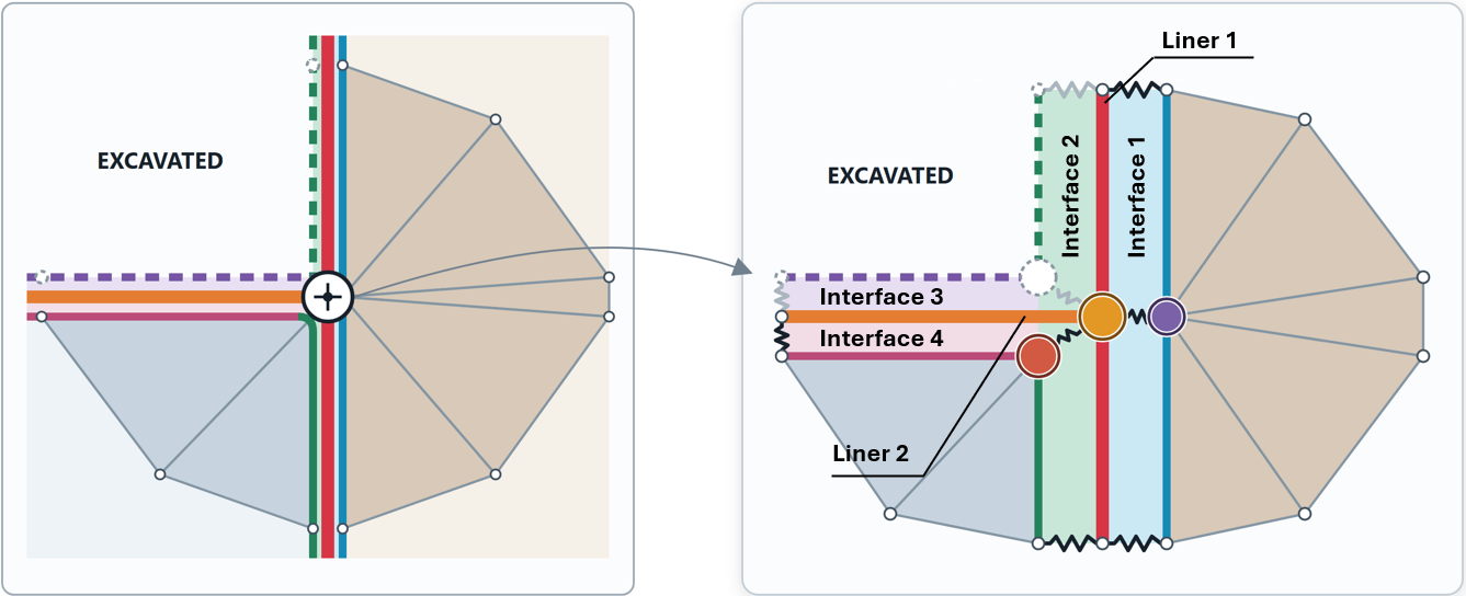
The same connectivity rules apply at a corner where two composite liners meet. The example below shows a vertical wall (represented by Liner 1) intersecting a horizontal base slab (Liner 2) in a deep excavation. Consider a staged excavation in which the walls are installed first, followed by excavation and subsequent installation of the base slab. The interface configuration must preserve the required liner connectivity as the excavation progresses
In this case:
- Interface 3 faces the excavation and is deactivated;
- the portion of Interface 2 above the slab also faces the excavation and is deactivated;
- Interface 4, the lower part of Interface 2, and Interface 1 remain active and connected to the liners.
Although some interface surfaces are removed or deactivated during the excavation sequence, both interface layers must be defined initially so that RS3 can generate the required shared node at the intersection of Liner 1 and Liner 2. Deactivating Interface 3 when the Liner 2 is installed does not remove the shared node. Consequently, the horizontal and vertical liners remain connected at the corner.
The figure below shows the corresponding case where the excavation-facing interface is omitted from the composite liner definition rather than being deactivated during the excavation stage.
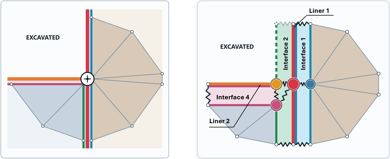
In this case, the excavation-facing interface (formerly Interface 3) is not available to establish the required connectivity during mesh generation. As a result, the Liner 2 can become disconnected from Liner 1 at the corner, even though the liner elements are geometrically coincident. If a connection between the horizontal and vertical liners is not intended, the composite liner should instead be defined explicitly with only the interface layers required for the desired connection.