Define Liner Local Coordinates
This feature is used to define a local coordinate system that will be used for all liner results when selected. It is recommended for walls or raft foundations where all liners are orientated in the same direction, but are not necessarily aligned with the global coordinate system.
When selecting Support > Liners > Define Liner Local Coordinates, users can define the local coordinates in two ways: select a Face or Edge, or Custom. Use the dialog options to define the local coordinate system.
Face or Edge
This option defines the liner local coordinate system based on the selected face or edge.
Face Selection
Follow the steps to use Face Selection:
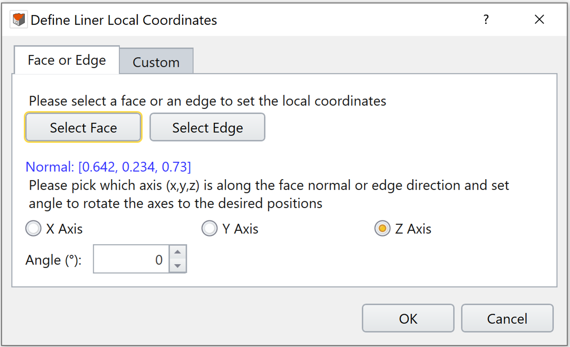
1. Under the Face or Edge tab, click on the “Select Face” button.
2. Select a face in the viewport. A liner local coordinate system will be set based on the selected face. The normal vector to that face is shown in blue text.
3. To change the local axis defined by normal vector to the face, select the radio button corresponding to the local X, Y or Z Axis. The remaining axes are defined by the right-hand rule.
4. To rotate the local axes about the normal vector to the face, input the rotation angle in degrees. The rotation follows the right-hand rule where the thumb is the normal vector to the face and the fingers curl in the direction of positive rotation. For example, if the normal vector to the face is pointing out of the screen, a positive rotation angle would result in a counter-clockwise rotation.
Edge Selection
Follow the steps to use Edge Selection:
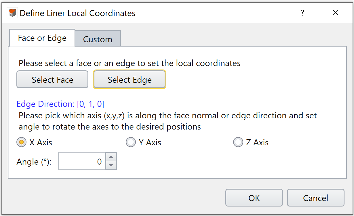
1. Under the Face or Edge tab, click on the “Select Edge” button.
2. Select an edge in the viewport. A liner local coordinate system will be set based on the selected edge. The vector defining the edge direction is shown in blue text.
3. To change the local axis defined by the edge direction, select the radio button corresponding to the local X, Y or Z Axis. The remaining axes are defined using the right-hand rule.
4. To rotate the local axes about the edge direction, input the rotation angle in degrees. The rotation follows the right-hand rule where the thumb is the edge direction and the fingers curl in the direction of positive rotation. For example, if the edge direction is pointing out of the screen, a positive rotation angle would result in a counter-clockwise rotation.
Custom
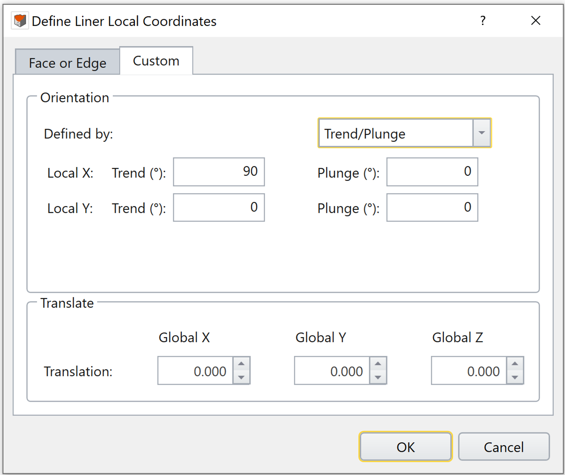
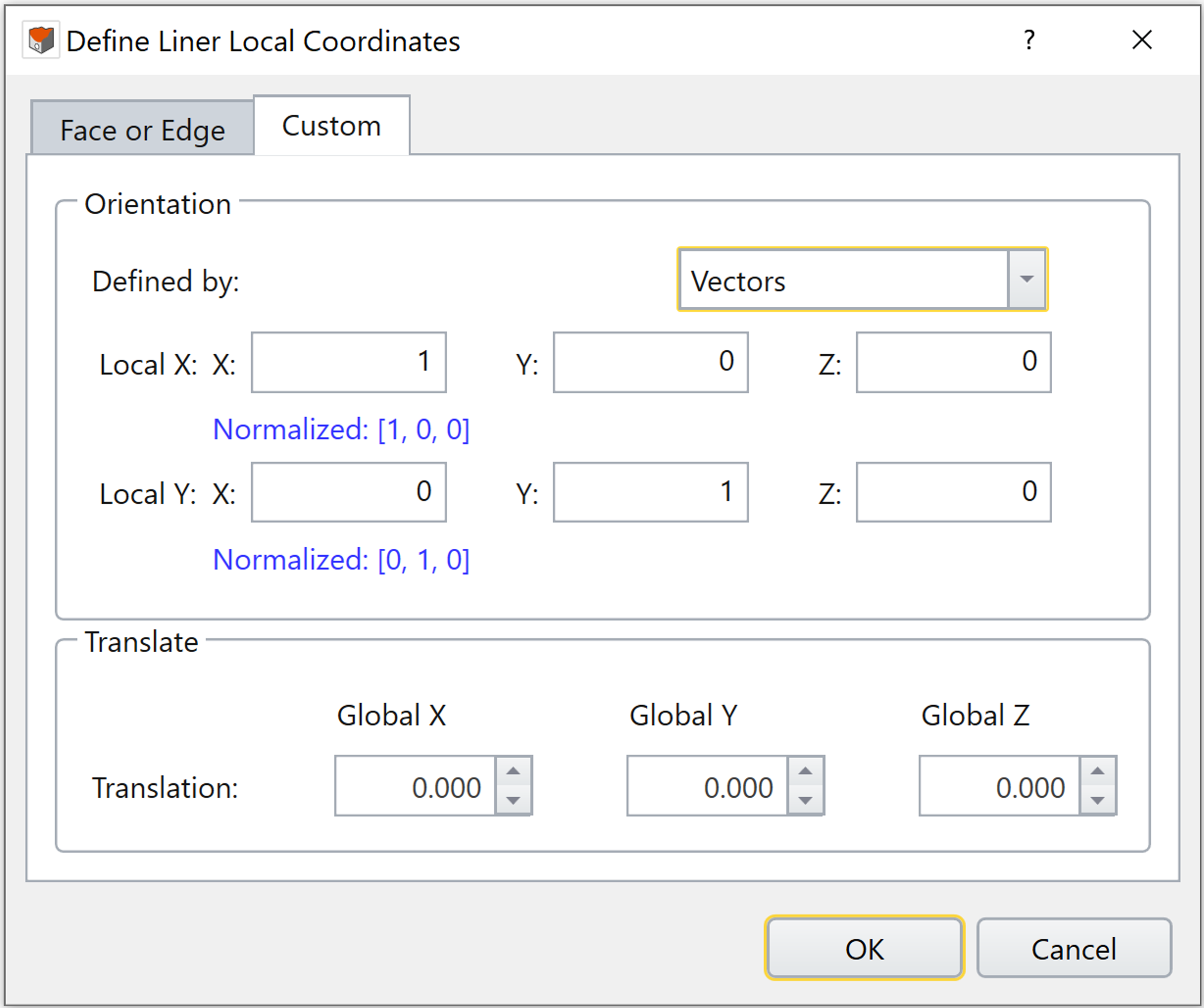
With Custom, the liner local coordinate system can be set freely without selecting any geometry. The orientation can be defined by either inputting trend and plunge angles, or by inputting a vector. In the Translate section, you can define the origin of the liner local coordinate system by entering the global x, y and z coordinates. By default, the origin of the liner local coordinate system is assumed to be at (0, 0, 0). Translating the axes allows better visualization of the local coordinate system on your model and does not affect the calculation of liner results.
Use either method to define the Orientation:
- Choose Defined by = Trend/Plunge – specify a trend angle and a plunge angle for each of local X and Y axis directions. Note that the local X and Local Y axes must be orthogonal to each other. See the help page Sign Convention - Trend/Plunge for trend/plunge sign convention in RS3.
- Choose Defined by = Vectors – specify a vector with XYZ components for each of local X and Y axis directions. The normalized vector will be shown below in blue text.
|
|
Click OK to create the liner local coordinate system. A new frame entity is created under the visibility tree. All liner results will be converted to the frame’s local coordinate system. To view and interpret liner results in local coordinate, please see Composite Liner Results Overview.
Example
An example to illustrate the Define Liner Local Coordinate application process is given below.
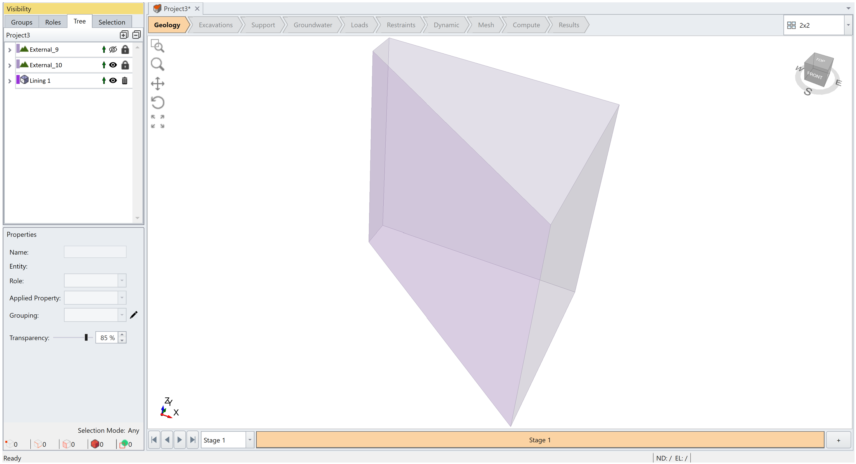
In the model, the cut surface is supported with liners. To view liner results in the local coordinate system, a frame entity is created using the Define Liner Local Coordinate feature. Face Selection method is used in this example.
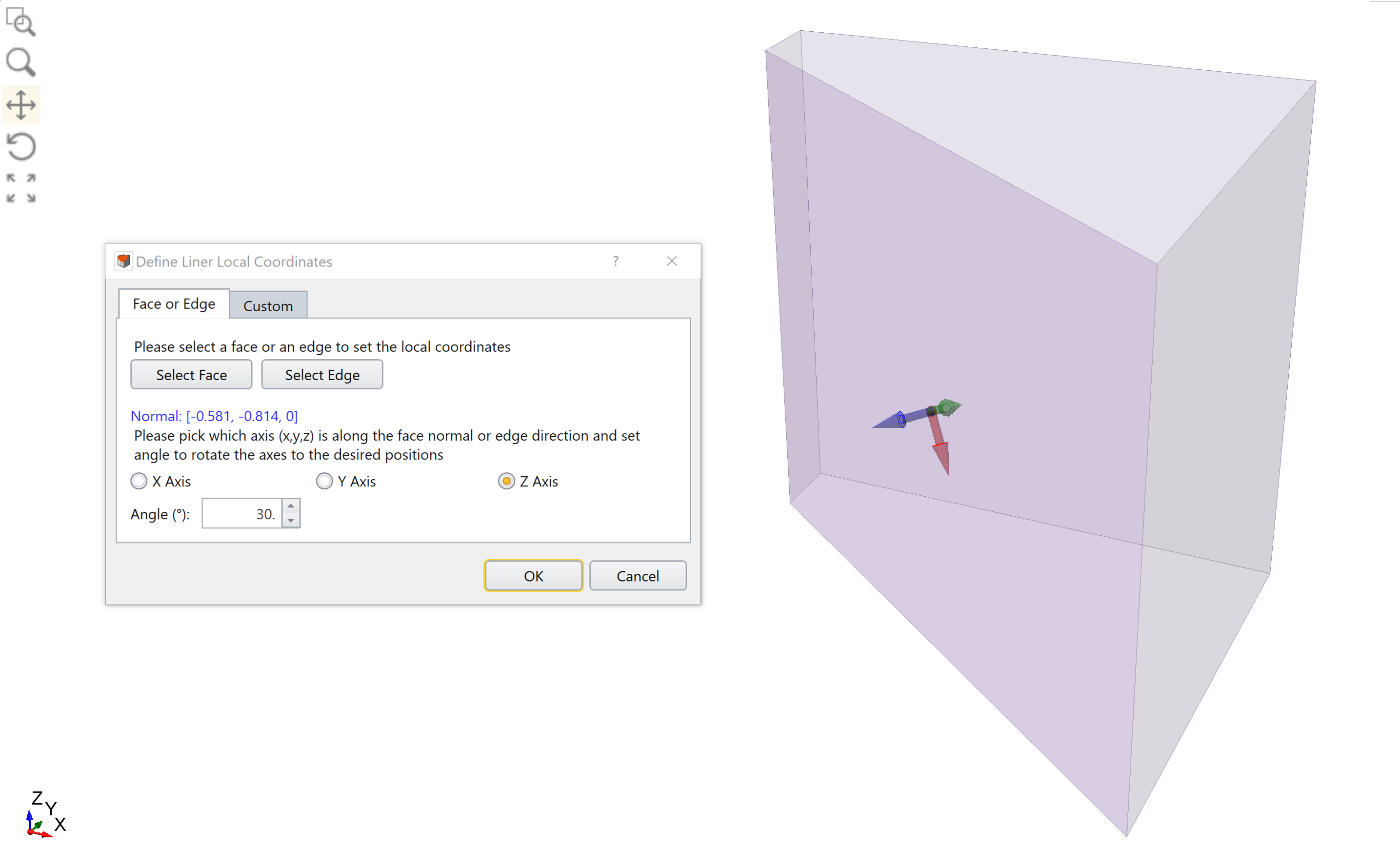
As seen in the picture below, the normal vector to the face is [-0.581, -0.814, 0]. A new liner local coordinate frame is created, with local Z axis normal to the face. The local X and Y-axis are rotated 30 degrees counter-clockwise about the positive local Z axis (normal vector to the face). A GIF animation is also provided below.
To view and interpret liner results in local coordinate, please see Composite Liner Results Overview.