Define DFNs
The Define DFNs option allows users to define one or more DFN set(s) before applying to the model. Each DFN set can be comprised of one or more types of DFNs, including parallel DFN, cross-jointed DFN, and externally imported DFNs.
To define DFN set(s):
- Select the Define DFNs
 option under the Discrete Fracture Networks (DFNs) sub-menu from the Materials menu. You will be prompted to a dialog.
 - In the Define DFNs dialog, an empty DFN set is added to the list by default. See more details about the Dialog Layout.
You can double click on the item to rename, and use the icons at the bottom of the list to Add , Delete
  , or Duplicate
  a DFN set.
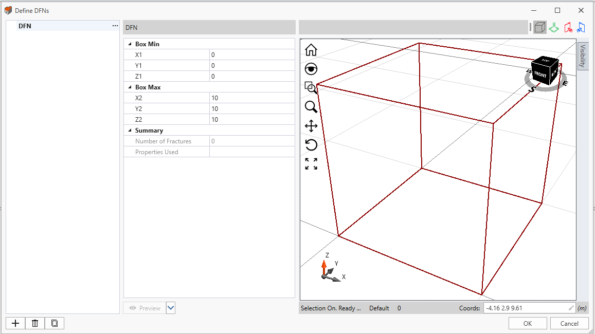
 - For the empty DFN set, a box is created as the DFN set boundary. You can set the values to change box dimensions in the dialog. Note:
- If there is no external volume in the model, a default box dimensioned 10x10x10 is created. If there is an external volume the dimensions of the box would be adjusted accordingly based on the size of the external.
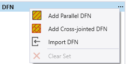
- Select the “…” icon for the DFN set, and select one type of fracture network from the dropdown menu to add (as shown in the screenshot below):
- Add Parallel DFN
- Add Cross-jointed DFN
- Import DFN
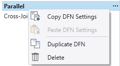
- Select the DFN from the list. You can double click on the item to rename. Use the “…” button to Copy
 , Paste
  , Duplicate
  , or Delete
  the DFN.
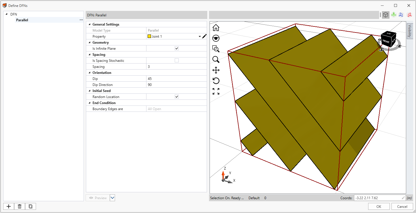
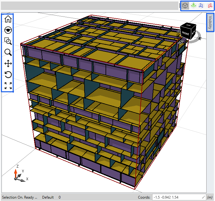
 - Define the properties in the setting panel. The joints will be highlighted in the viewport panel. Below shows an example of parallel DFN.
- Multiple DFNs can be defined within each DFN set, and multiple DFN sets can be defined in the dialog.
When completed, select OK to save and exit the Define DFNs dialog. - Now we can add the defined DFN sets to the model with the Add a DFN option. See the linked topic for more details.
The selected DFN will be added to the DFN set. For more information of each type, see the Parallel DFN, Cross-jointed DFN, and Import DFN topics.
Dialog Layout
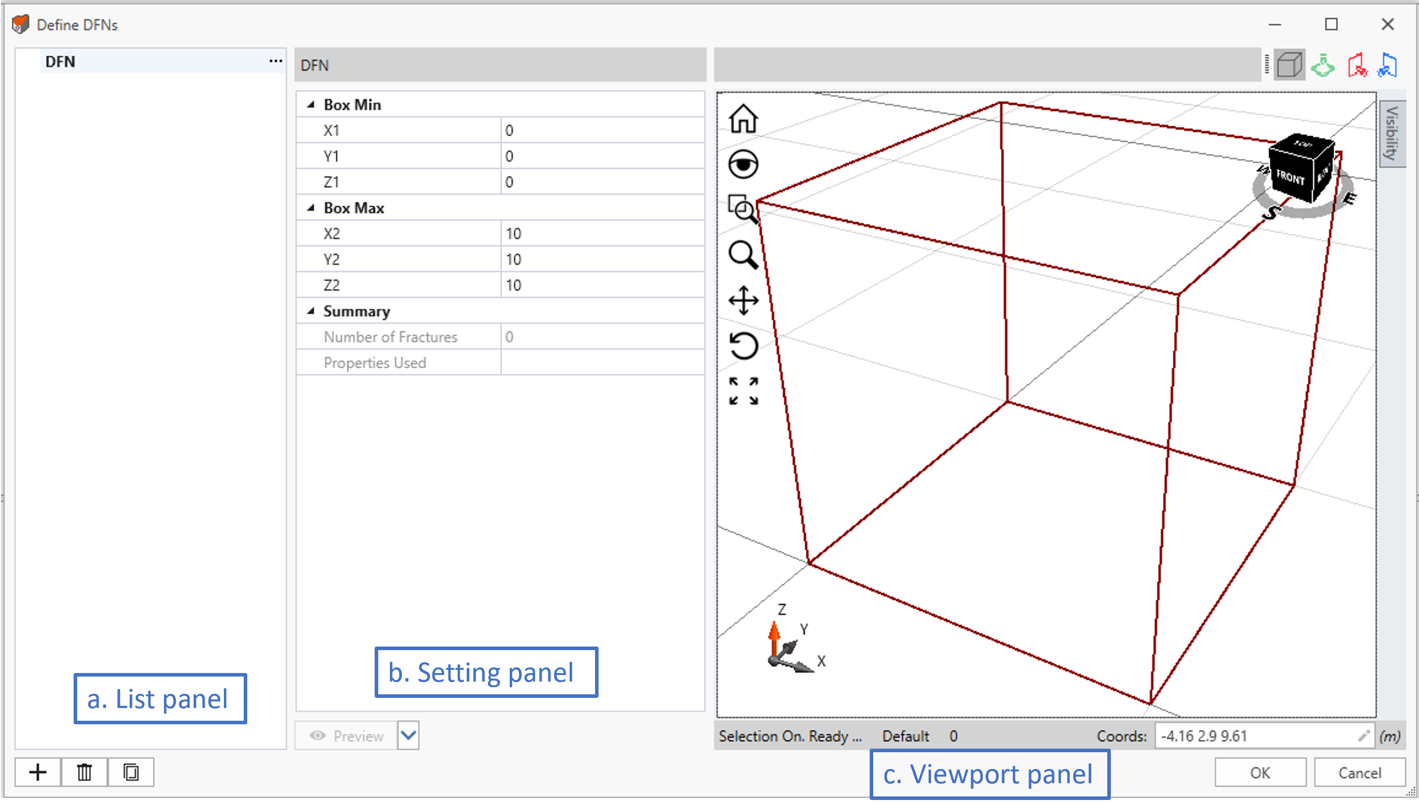
The Define DFNs dialog is divided into three parts, they are from left to right:
- the list panel contains defined DFN items.
- the setting panel:
- lists out the box dimensions and summary for the DFN set (see image above)
- specifies the properties for individual DFNs (i.e., parallel, cross-jointed, and imported) (see image below)
- the viewport panel displays the selected DFN set view. See the Viewport Panel section below for details.
Viewport Panel
As labelled in the screenshot below, the Viewport Panel in the Define DFNs dialog contains:
- a Viewport displays the DFN model
- a Visibility sidebar lists all entities in the DFN set, and allows to show/hide the entities.
- a Toolbar with four viewing options about the bounding box and cutting planes within.
Viewport
The viewport displays the currently selected DFN set. You can choose to show/hide entities in the Visibility section. Click the Preview button in the dialog to update changes to viewport. You have various options to adjust the view in the viewport:
- Home
 returns the view axis orientation and zooms back to the default position while trying to ensure all tunnel features are visible and the largest possible size in the viewport
 - Magnifying Glass
 creates a small, zoomed-in window that can be moved using the mouse
 - Zoom Window
 allows you to zoom into a specific region of the model that is drawn using the mouse by left-clicking, dragging and releasing
 - Zoom
 allows you to zoom into a specific point of the model that is drawn using the mouse by left-clicking, dragging and releasing
 - Pan
 allows you to move the view without rotating the model
 - Rotate
 allows you to change the view angle of the model
 - Zoom Fit
 adjusts the view to ensure all tunnel features are visible and the largest possible size in the viewport
 - View Cube
 has options for easier adjustment of the model view
Visibility
The Visibility section allows you to choose which entities of the DFN set to be displayed in the viewport.
Expand the Visibility sidebar, all entities contained in the DFN set are listed. It includes the bounding box, all DFNs, and the cutting planes created with the Toolbar. By default, all components are toggled on. Check/uncheck an item to show/hide in the viewport. You can Pin ![]() the Visibility section in the dialog. A GIF animation is provided below.
the Visibility section in the dialog. A GIF animation is provided below.
Toolbar
There are more view options at the top of the viewport. The Show Bounding Box ![]() option is toggled ON by default. It shows the bounding box of the DFN set, where the dimensions are defined under the DFN set item (see the image above).
option is toggled ON by default. It shows the bounding box of the DFN set, where the dimensions are defined under the DFN set item (see the image above).
You can also view cutting planes within the box using the Add XY Section ![]() , Add YZ Section
, Add YZ Section ![]() , and Add XZ Section
, and Add XZ Section ![]() options. The created plane will be added under the Visibility list at the sidebar. To use the options:
options. The created plane will be added under the Visibility list at the sidebar. To use the options:
- Toggle on the Add XY Section
 option, in the viewport, a XY cutting plane inside the box will appear with a Freehand Manipulation Tool
  at the center of the plane.
 - For the Freehand Manipulation Tool, you can drag the arrow to move the plane along Z axis; drag and rotate the green and red circles to rotate the plane around the Y axis and X axis respectively; drag the middle orange ball to relocate the Freehand Manipulation tool anywhere on the plane surface, or translate the plane in the direction normal to the plane.
- Toggle off the Add XY Section option to exit the plane. Switch to Add YZ Section or Add XZ Section option to switch the plane orientation.
- A GIF animation is provided below.
The Add YZ Section ![]() and Add XZ Section
and Add XZ Section ![]() options are the same as the Add XY Section option as described above. Except that for the Add YZ Section option, the initial plane orientation is YZ, the arrow moves along the X axis, and the two circles rotates around the Z and Y axes; for the Add XZ Section option, the initial plane orientation is XZ, the arrow moves along the Y axis, and the two circles rotates around the X and Y axes.
options are the same as the Add XY Section option as described above. Except that for the Add YZ Section option, the initial plane orientation is YZ, the arrow moves along the X axis, and the two circles rotates around the Z and Y axes; for the Add XZ Section option, the initial plane orientation is XZ, the arrow moves along the Y axis, and the two circles rotates around the X and Y axes.
Preview
The Preview option contains three sub-options under its dropdown list:
- Preview

- Randomize selected DFN

- Randomize Set

The first option is also the default option – Preview.
When a DFN is initially added, it will automatically preview in the viewport. Once parameters are changed, the DFN will become hidden and the preview needs to be done manually due to calculation complications. Select the Preview button or the first item on its dropdown list, the updated DFN set will be shown in the viewport with their updated settings. Note that the random variable will not be re-generated with the Preview option, which is only involved in the Randomize selected DFN and Randomize Set options.
Randomize
For the second and third options, other than updating the setting changes to preview, they are also available for randomizing, which are only subjected to the parameters defined with statistical distributions.
The Randomize selected DFN option allows you to randomize the currently selected DFN. The Randomize Set allows you to randomize the currently selected DFN set. The updated view with changed settings and changed random variables will be displayed to the viewport.
When a DFN set is generated, random sampling of statistical distributions may be used to generate the joint length, spacing and other parameters. The actual random variables will depend on the joint models and the variables to which a statistical distribution has been assigned. In most cases, one or more random variables will be used to generate a DFN set.
When a DFN set is initially generated, the resulting network is determined by an initial random sampling of the random variables.
You can re-generate a new network at any time by clicking either of the two Randomize options. This will re-sample all random variables of your joint models and generate a new DFN set, based on the statistical distributions of the random variables you have defined. The Randomize option can be used at any time to re-generate a joint network, or if you simply wish to visualize the changing joint networks which result from repeated random sampling.
Statistical Distribution or Constant Value
If you are defining a DFN (i.e., parallel DFN or cross-jointed DFN) in RS3, The some parameters can be defined with either statistical distributions or constant values, which is controlled by the option of “Is (Parameter) Stochastic”.