Elevation Load
Elevation distributed loads, which vary linearly between two points of different elevation (i.e. the z-coordinate of each point differs) along a boundary, can be applied to edges or faces with both the Define Projected Load option and Add Loads to Selected option by specifying Elevation Load as the Load Type. The load distribution is treated as triangular (zero at one end) or trapezoidal (different non-zero values at each end) based on the user-specified Top Magnitude/Delta and the elevation of the boundaries.
To apply an Elevation distributed load to a face:
- Select the Loads workflow tab

- Select Faces Selection
 as the Selection Mode.
 - Select the face(s) on which to apply the load.
- Select Add Loads to Selected
 from the toolbar or the Loading menu.
 - You will see the Add Load to Selected dialog. In this dialog:
- select the Load Type = Elevation Load
- enter the Top Magnitude/Delta of the load
- and specify the load Orientation (e.g. Normal, Local +x, Local +y, Local +z, Vector (x,y,z), or Trend/Plunge)
- in a multi-stage mode, the Staging options allow you to specify the stage at which the load will be installed and the stage at which the load will be removed. Elevation distributed loads can be staged by selecting the Stage Factors checkbox, and entering a Magnitude Factor for the load magnitude at each stage. If you do not stage the load on a multi-stage model, then the load will be applied with the same magnitude at all stages.
See below for details about the load magnitude, orientation, and staging.
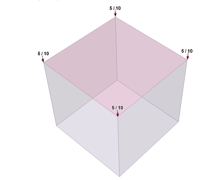
- When finished specifying the load properties and the preview of the applied load, as indicated by the display of green arrows, is as desired, select Apply. The Elevation distributed load will be applied to the selected face(s), as indicated by the display of red arrows and the magnitude.
- Check the direction of the arrows and the magnitude, to make sure that this is the load you wished to apply. If there is a mistake, you can repeat the above steps to apply the correct load, or select and edit the load using the Properties Pane to change the load parameters.
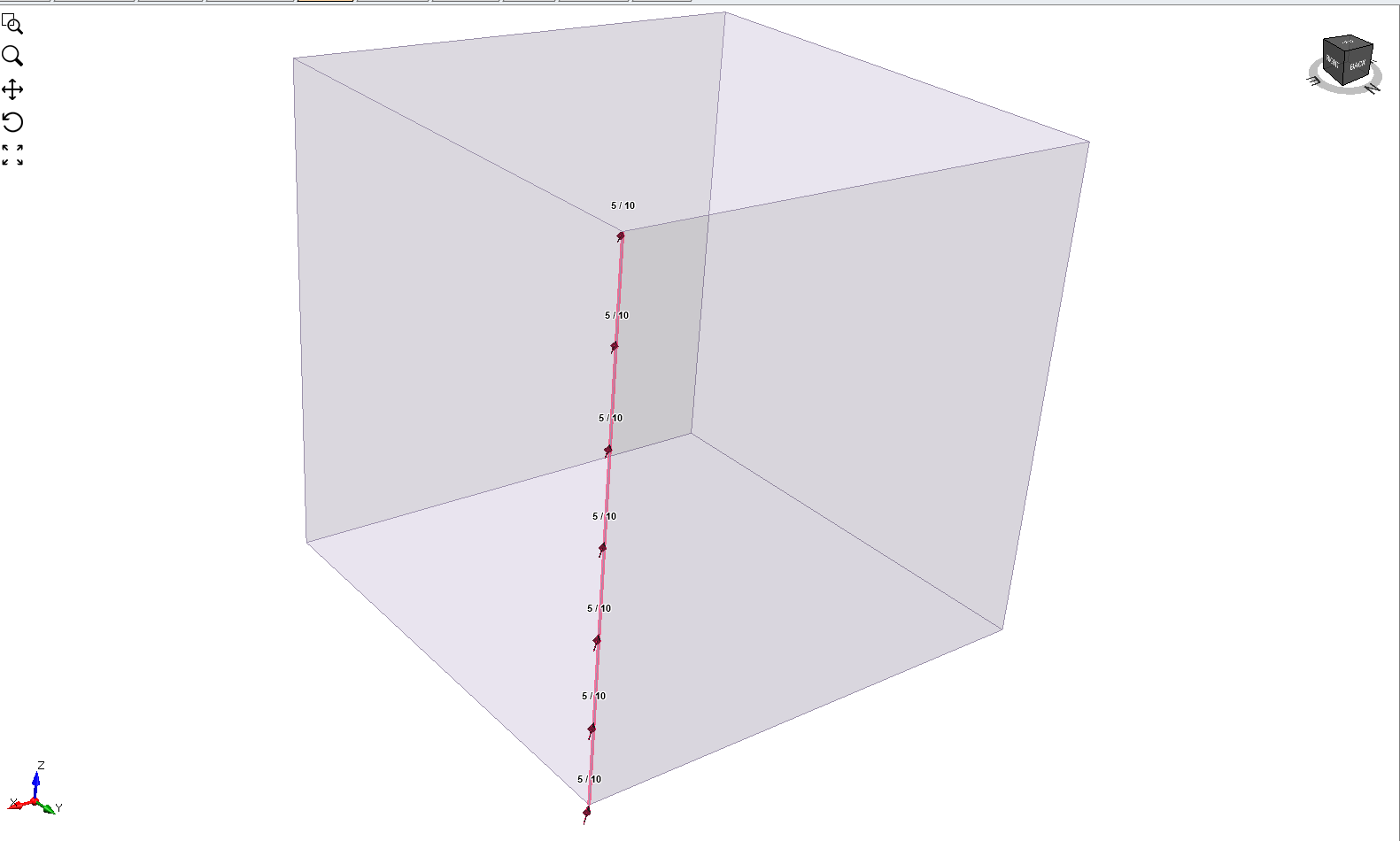
To apply an Elevation Load to an edge (line load) repeat the Steps 1 to 7, but use Edges Selection  to select the edge(s) on which to apply the load.
Although it is possible to select to apply an Elevation Load to a single vertex (point load), it is recommended that Uniform Load be selected for such an operation, as, by definition, there will be no change in elevation for the load applied to a single vertex.
TOP MAGNITUDE/DELTA OF LOAD
The Top Magnitude is the magnitude of the load that will be applied at the top, or highest point, of the selected boundary (edge or face). The Delta is the change in the load magnitude per unit decrease in elevation.
- Delta = 0 means that the magnitude of the load does not change with a decrease in elevation (z-coordinate). This type of Elevation Load is equivalent to a Uniform Load.
- Delta > 0 means that the magnitude of the load increases as the elevation of the boundary decreases (i.e. the load magnitude at the bottom of the boundary is greater than the Top Magnitude).
- Delta < 0 means that the magnitude of the load decreases as the elevation of the boundary decreases (i.e. the load magnitude at the bottom of the boundary is less than the Top Magnitude)
LOAD MAGNITUDE
A distributed load magnitude is generally entered as a positive value. The direction of load application is specified by selecting an appropriate Orientation method (see below) in the Add Load to Selected dialog. If a negative load magnitude is entered, the direction of the applied load will be reversed.
LOAD ORIENTATION
For details about defining the load Orientation, see the Uniform Load topic, as the same information applies to both Uniform and Elevation loads.
STAGING DISTRIBUTED LOADS
On a multi-stage model, distributed loads can easily be staged by selecting the Stage Factors checkbox in the Add Load to Selected dialog (Step 5 above). You will see Stage Magnitude Factors in the expanded dialog. Select the Add Stage  button for each stage and enter a Magnitude Factor for the load at each stage. The Magnitude Factor is multiplied by the load magnitude to obtain the actual load magnitude used at each stage (e.g. if the Magnitude Factor = 0.2 and the load magnitude = 5, then the actual load magnitude applied at that stage will be 0.2 * 5.0 = 1.0). This allows you to increase or decrease the applied Elevation distributed load applied at any stage. NOTE:
- Magnitude Factor = 1 means that the load magnitude will be equal to the magnitude(s) entered in the Add Load to Selected dialog.
- You can increase or decrease the load at any stage, by entering a Magnitude Factor greater than or less than 1 (e.g. a Magnitude Factor = 2 would double the load magnitude at all points along the boundary).
- You can remove the load at any stage, by entering a Magnitude Factor = 0. The load will not exist in any stage in which the Magnitude Factor = 0, and will not appear on the model.
If your load is staged, it is a good idea to select the Stage Tabs, after adding the load, to check that the load is applied at the correct stages, and that the magnitudes are correct. If not, then repeat Steps 1 to 7 (above) or select and edit the load using the Properties Pane, and make sure that the correct Magnitude Factors have been applied at the correct stages.