Selecting
For many options in RS3, you are required to select aspects of an entity on the screen while creating and editing the model, for example:
- Geometry, for editing, applying loads, etc.
- Support (e.g. bolts, liners, piles) for editing
- Loads
Here are some useful tips to remember when selecting.
General Rules
When an entity is selected, it will temporarily change colour or line style to indicate that it is selected. For example, selecting any geometry changes the selected vertex, edge, surface or entity to an orange colour.
Selection Mode
There are several Selection Mode  options available in the toolbar or Edit menu you can use to capture the desired entity, face, edge or vertex. Only Geometry Entities can use the face, edge or vertex selection options.
- Entity Selection
 : Select the entire entity.
 - Faces Selection
 : Select a plane on a Geometry Entity .
 - Edges Selection
 : Select a line on a Geometry Entity .
 - Vertices Selection
 : Select a point on a Geometry Entity.
 - Face, Edge, Vertex Selection
 : Select the closest face, edge or vertex to your cursor. If you are not hovering over a Geometry Entity, the selection will default to Entity selection mode. If you double-click a Geometry Entity you will select the entire Entity .
 - Disable Selection
 : no further item in the program will be selected, but you will not lose the previously selected items.
Clear Selection
You can also clear all selections using the Clear Selection  option in the toolbar or Edit menu.
Selection Region Mode
There are several Selection Region Mode  options available in the toolbar or Edit menu to select groups of desired entities, faces, edges or vertices by drawing a selection region around them using the mouse. Only Geometry Entities can use the face, edge or vertex selection options. To draw a selection region, do the following:
- Hold down left-click and drag the mouse to draw a region.
- Release the left-click when you have finished selection.
- Based on the Selection Mode , the entities, faces, edges and/or vertices that touch the highlighted region will be selected.
The regions can be drawn as the following shapes:
- Rectangle : rectangular shape.
- Lasso
 : freehand shape where the start and end points do not need to touch.
Below is an example where the Selection Mode is set to vertex only and a Rectangle Selection Region Mode (left) is compared to a Lasso Selection Region Mode (right):
| Rectangle Selection Region Mode | Lasso Selection Region Mode |
 |  |
Selection from Visibility Pane
You can select any Entity in the Visibility pane.
- When you select entities this way, it will automatically be an Entity select.
- In the Groups tab of the Visibility pane, you can use the checkboxes to the right of any entity or simply click on the entity name to select the Entity. The entities are arranged according to their application type such as Geology, Groundwater etc.
- In the Tree tab of the Visibility pane, you simply click on the entity name to select the Entity.
Special Select from Right-Click Menu
There are three special selection tools available in RS3 that can be available using the right-click menu.
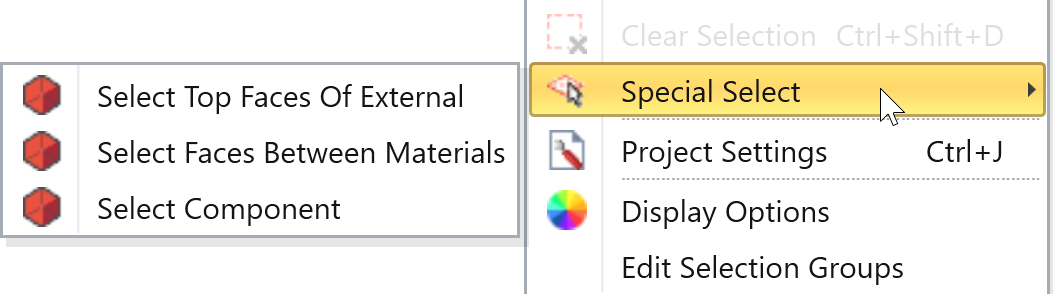
Select Top Faces of External
This is a convenient option to quickly select the top faces of the model. This option is not available if the model does not have an external volume. The location of the mouse cursor when you use this option determines the top faces selected:
- If you hover over the empty space in the viewport, this option selects ALL top faces of the model
- If you hover over a specific external piece, this option tries to select the top faces of the model associated with this particular piece
- If you hover over an external piece where no faces are at the top of the model, this option does not select any faces
- If you hover over non-external geometry, this option does not select any faces
Select the Faces Between Materials
This is a convenient option for the user to quickly select the shared faces between two divided pieces. The use case of this lies in adding surfaces such as joint surfaces, or slide3 surface types that were meant to specify properties between the specific boundaries between materials.
Select Component
To enable the option, do the following:
- Hover over a face with Face, Edge, Vertex Selection or Face Selection mode ON.
- Right-click the face
- Special Select > Select Component
- The program will automatically select all faces created from the same geometry