Tunnel Path
For tunnel design, the tunnel path should be defined after the Tunnel Profile is specified. The Path option adds the depth dimension to the tunnel profile, transforming the 2D design to 3D. The tunnel path can be defined with four methods: extrude, coordinates, import (*.dwg or *.dxf), or draw planar path. A partial path can also be added.
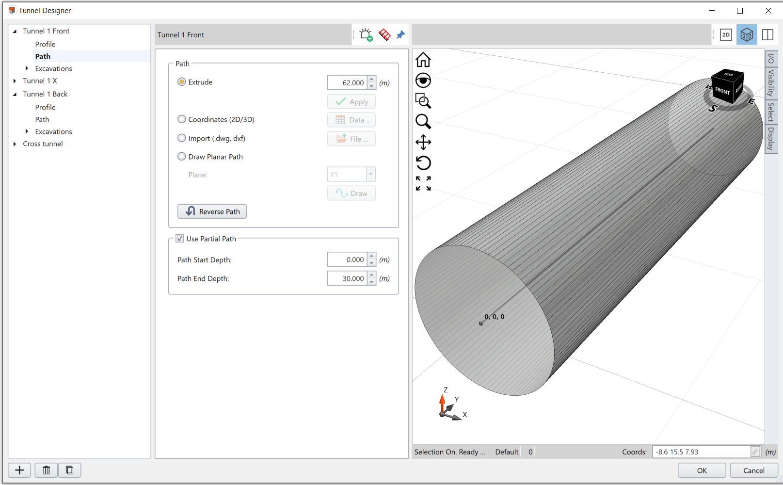
Select Path under the Tunnel Design list in the left side of Tunnel Designer dialog. The viewport will be switched to 3D automatically.
Methods
Extrude
You can use the Extrude option to extend the polyline or surface along the axis perpendicular to the 2D axes with a depth. Select the Extrude option, enter a depth value, and select Apply. The 3D tunnel will display in the viewport.
Coordinates (2D/3D)
You can define a path by inputting the path coordinates. You can trace a path by defining the coordinates. Select the Coordinates (2D/3D) option and select the Data button. It will open a spreadsheet window. Input x, y, and z coordinates of the path in the spreadsheet cells starting from the top left cell (A1). Alternative, you can import data file with the format *.xlsx, *.csv, or *.txt. to the spreadsheet. The axes directions are shown in the 3D viewport.
See RS3 Tutorial – Tunnel Design with Boreholes for and example of using coordinate table to define tunnel path.
For more information about the data table in tunnel designer, see the I/O section of the Toolbar topic.
Import (.dwg, .dxf)
The Import option allows you to import a file of tunnel path drawing. Supported file formats are *.dwg and *.dxf. The path drawing should be a single open (i.e. it does not form a loop or intersects itself) curve in 2D or 3D space.
For the imported file, curves including polylines, lines, arcs, etc. are allowed. RS3 will try to connect all curves into one curve, and use it as the tunnel path.
If RS3 cannot extract a single open curve, a message of “No Path to Import” will display. If RS3 finds more than one possible path in the file, a message of “Can not determine path to import” will display.
Draw Planar Path
The Draw Planar Path option allows you to manually draw the tunnel path on a 2D plane.
To use the option:
- Select the Draw Planar Path option under the Path tab
- Select a Plane of your path profile drawing, from the dropdown menu (Plane = XY, XZ, or YZ).
- Click on the Draw button. Now you can manually create the 2D path profile as a polyline.
In the 2D viewport, the coordinate system has been changed from XY to a local UV system. The UV system represents the chosen Plane from step 2. The tunnel profile will be placed orthogonal to the path plane. Therefore, as seen in the middle of the viewport, the dark red line is the outer of tunnel design from top view, and the grey square is the reference point.
The polyline tool will be initiated. Use one of the following methods to create the path: - Use the mouse to select distinct locations, starting from the tunnel profile. Click Enter or right-click Done to finish.
Tip: Zoom in and out with the mouse wheel to draw freely. - Enter the coordinate of the path in the coordinate bar. Click Enter or right-click Done to finish.
- Right click and select Edit, enter a table of coordinates in the popup excel sheet, and select OK to apply.
- The extruded tunnel will be displayed in the 3D viewport. See image 2 for an example.
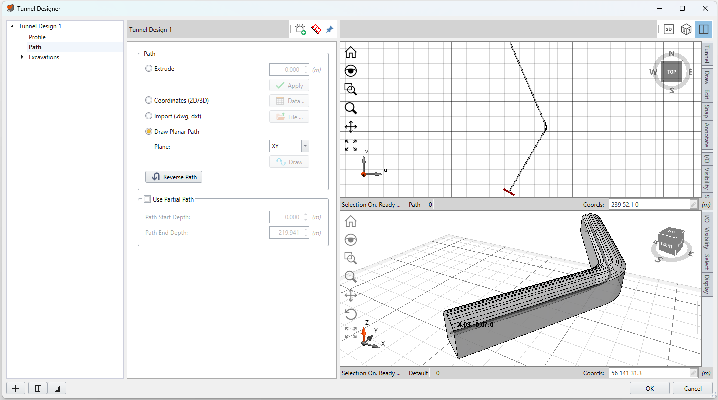
Image 2. An example of the Draw Planar Path option
The start point of the path will be the reference point of the tunnel profile. The tunnel profile will be orthogonal to the path direction. When the path is a polyline, RS3 will automatically modify the sharp turns into curves (as shown in image 2 above).
Right-click Context
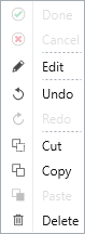
Select the planar path in 2D viewport, and the path will be highlighted in red. Right-click on it, you can Edit, Undo, Cut, Copy, or Delete the path.
Select Edit from the context menu, an Edit Points
excel spreadsheet window will pop up. The coordinates of the path are displayed. Edit the coordinates to modify the path
Reverse Path
The Reverse Path option allows you to reverse the path direction. When it is selected, the other end of the path will be defined as the start point (i.e. Y=0).
Use Partial Path
The Use Partial Path option is used to truncate a tunnel into sections along the path. It is helpful when you want to apply a tunnel to the model as separate sections. This option is usually used together with copying and pasting a tunnel design (the duplicate option is at the bottom left corner  )
)
To design and apply a truncated tunnel with the Use Partial Path option,
- In the Tunnel Designer dialog, create a tunnel design with the complete design (i.e. with a complete path, and include all settings such as excavation sequencing, supports and load).
- Duplicate this tunnel design for multiple times with the copy and paste option.
- For each tunnel design, select the Use Partial Path option, and define the start and end point within the defined path.
- Now, all tunnel design items will have the same settings, except for the path length.
- Apply each item to the model with the Add a Tunnel option, it will show as a tunnel with discontinuities.
For example, a 90m tunnel has cuts at 20m and 70m, then three tunnel items should be created, all of them have the full path defined, while having Use Partial Path option checked with 0-20m, 20-70m, and 70-90m defined respectively.
In the Tunnel Designer dialog, to show multiple tunnel designs in the viewport, you can use the Pin  option at the top of the middle pane. See the Pin section in Tunnel Designer Overview for more detail.
See RS3 Tutorial - Cross-Section Tunnel Design for the an example of the Use Partial Path option.