Define Projected Loads
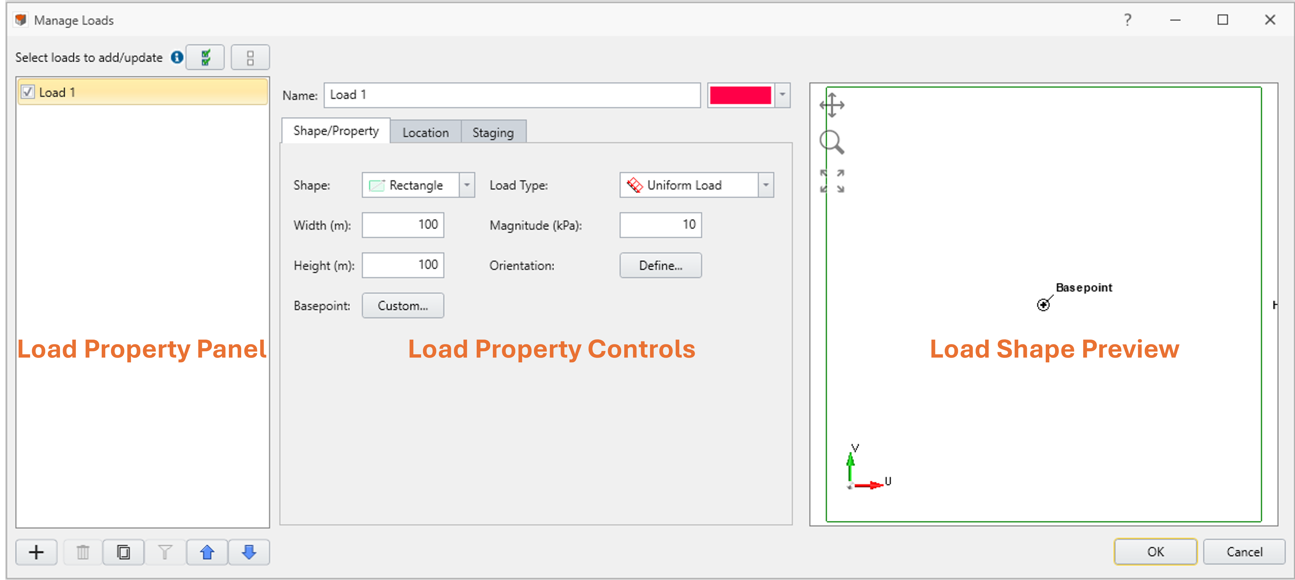
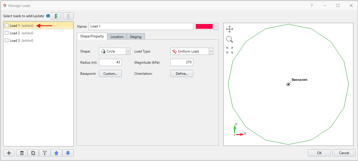
Accessible under the Loading menu in RS3, the Define Projected Load command opens the Manage Loads dialog, shown below. This dialog serves as the main interface for creating, saving, and editing loads to be projected onto an external volume’s surface.
The Manage Loads dialog is broken down into three sections:
- Load Property Panel,
- Load Property Controls, and
- Load Shape Preview
Load Property Panel
This panel displays a list of load property samples. These samples store all necessary information to generate a load entity in the model. When a load entity is generated using the information stored in one of the samples, the entity’s name follows that of its sample counterpart and forms pairing between the two. From the Load Property Panel, users can:
- add or remove samples from the list;
- sort and manage samples; and
- select which samples to add to the model or update using checkboxes
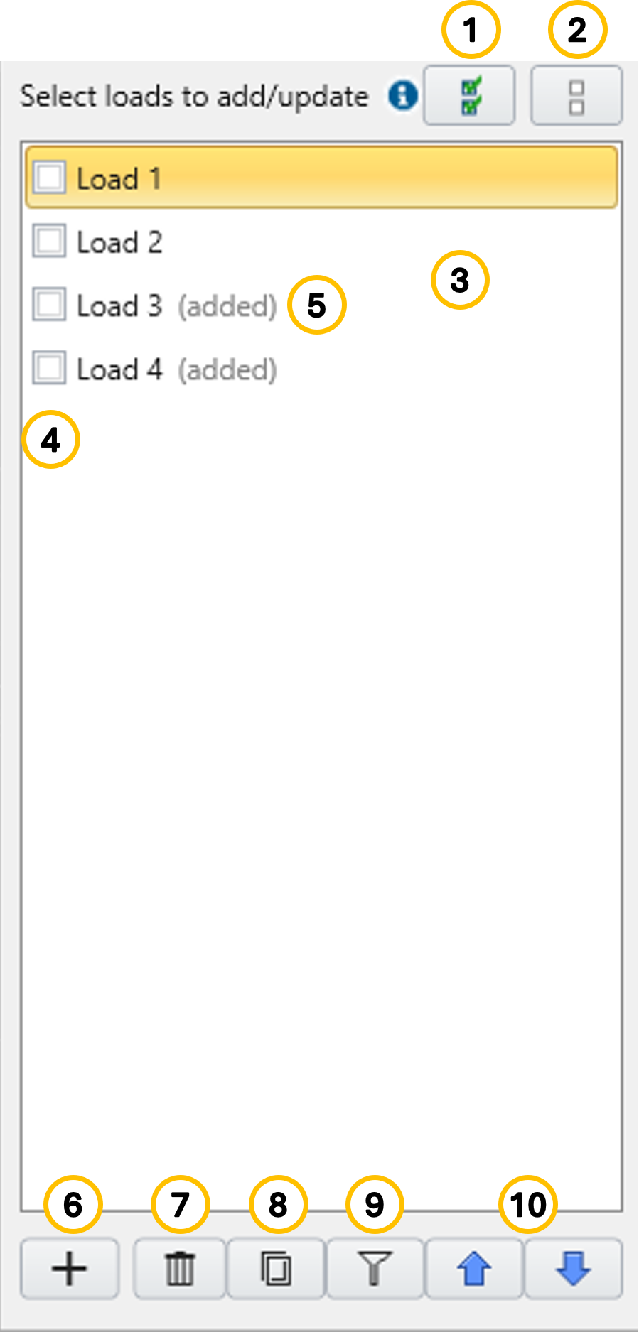
Legend:
- Check all load property samples
- Uncheck all load property samples
- Load property sample list to toggle between samples
- Check boxes to indicate to add the load property samples into the model or update the load entities paired with the sample existing load property samples in the model
- Load property sample that has the counterpart load entity existing in the model
- Add new load property sample
- Delete selected (not checked) load property sample
- Copy selected load property sample
- Filter active load property sample
- Move up/down the selected loads in the list
Each sample's configuration is modified using the Load Property Controls section described below.
Load Property Controls
The property of each sample is controlled in Load Property Control section. The section consists of Shape/Property tab, Location tab, and Staging tab. With respect to the inputs provided in Shape/Property tab and Location tab, the projector preview on viewport updates in automatically to reflect the current shape and location.
Shape/Property Tab
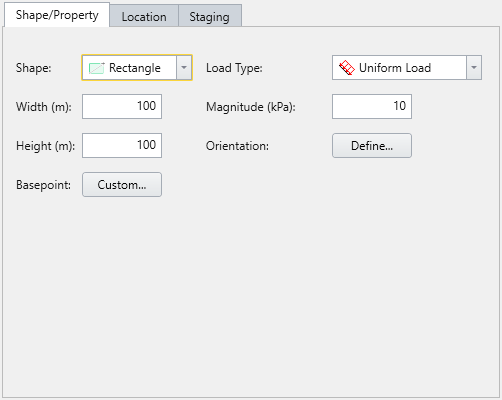
This tab provides sets of parameters to define the load's shape and key properties. The available shapes are:
- Rectangle
- Width (m) and Height (m)
- Magnitude
- Load Type (Uniform)
- Basepoint (default or custom)
- Orientation (vector, trend/plunge, normal, local +x, local +y, local +z)
- Circle
- Radius (m)
- Load Type (Uniform)
- Magnitude
- Basepoint (default or custom)
- Orientation (vector, trend/plunge, normal, local +x, local +y, local +z)
- Polygon (use table to enter custom coordinates)
- Basepoint (default or custom)
- Magnitude
- Orientation (vector, trend/plunge, normal, local +x, local +y, local +z)
- Coordinates [U(m) and V (m)]
The Load Shape Preview on the right side of the dialog updates in real time based on the current shape inputs, providing a visual reference for verification.
Base Point:
The base point is defined relative to the local coordinate system of the shape and determines how the shape maps to the model. The base point’s local coordinates (u, v) map to global coordinates (x, y). The U and V axes represent the local horizontal and vertical directions, shown to the right of the dialog.
Orientation:
This controls the load direction—not the surface projection direction—and can be set using:
- Trend/Plunge – specify using geological convention
- Normal – perpendicular to the surface
- Local +X/Y/Z – aligned to local coordinate directions
- Vector (X, Y, Z) – user-defined directional vector
Location Tab
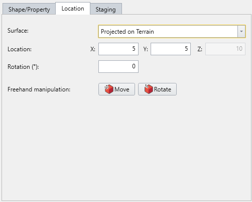
Surface:
- Projected on Terrain – projecting the load on the outermost top surface of the external volume
- Projected on Volume – projecting the load on a specific volume
- Volume: provides a list of existing external volumes to choose from
- Projection: lists projection directions (Top, Bottom, Left, Right, Front, Back, and Custom)
Location, Rotation, and Orientation:
Depending on the combination of surface parameter, availability for Location coordinate parameters accommodates, accordingly. For Custom projection mode, the orientation of the projector needs to be defined. For the Rotation and Location parameters, they can also be defined using Freehand Manipulations, interacting on the viewport.
Location Tab
Options here allow loads to be either placed freehand on the model using the Freehand Manipulation commands, or defined by coordinate on the modeling interface.
- Freehand Manipulation: these commands will minimize the large define load dialog and allow the user to place the load "Freehand" on the model
- Move Load: move the mouse around the modeling interface and click to place the load in the desired location
- Rotate Load: move the mouse to rotate the orientation of the load, using the center as the base
- Numerical Definition:
- Location: Enter the coordinates to define where the basepoint (previously defined in the Shape/Property tab) of the load will be located on the model
- Orientation: Enter an Angle to finalize the load definition. The load rotates with respect to the base point.
Staging Tab
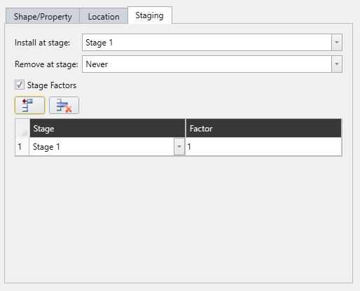
The staged behaviour of a selected load property sample can be defined under Staging tab. Under this tab, parameters are provided to manipulate Install stage and Remove stage, as well as stage factors.
- Install Stage: Stage when the load becomes active
- Remove Stage: Stage when the load is removed
- Stage Factors (optional):
- Enable stage factors using the checkbox
- Define different magnitude values for each stage
- If no factor is defined for a stage, the last defined magnitude is carried forward
How to Generate Projected Load Entities
- Prepare a Model – Ensure that your model includes at least one External Volume.
- Select Define Projected loads from the toolbar under Loads workflow tab
 or go to Loading > Define Projected Load from the main menu.
 - By Default, load property sample named “Load 1” appears in the Load Property Panel, already checked and selected for editing.
- Add more samples if needed and define the properties of them (GIF below shows three samples with different properties applied):
- Check the check box of load property samples to add or update in the model.
- Click OK to apply the defined load(s) to the model.
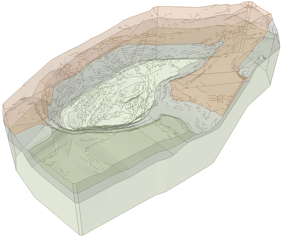
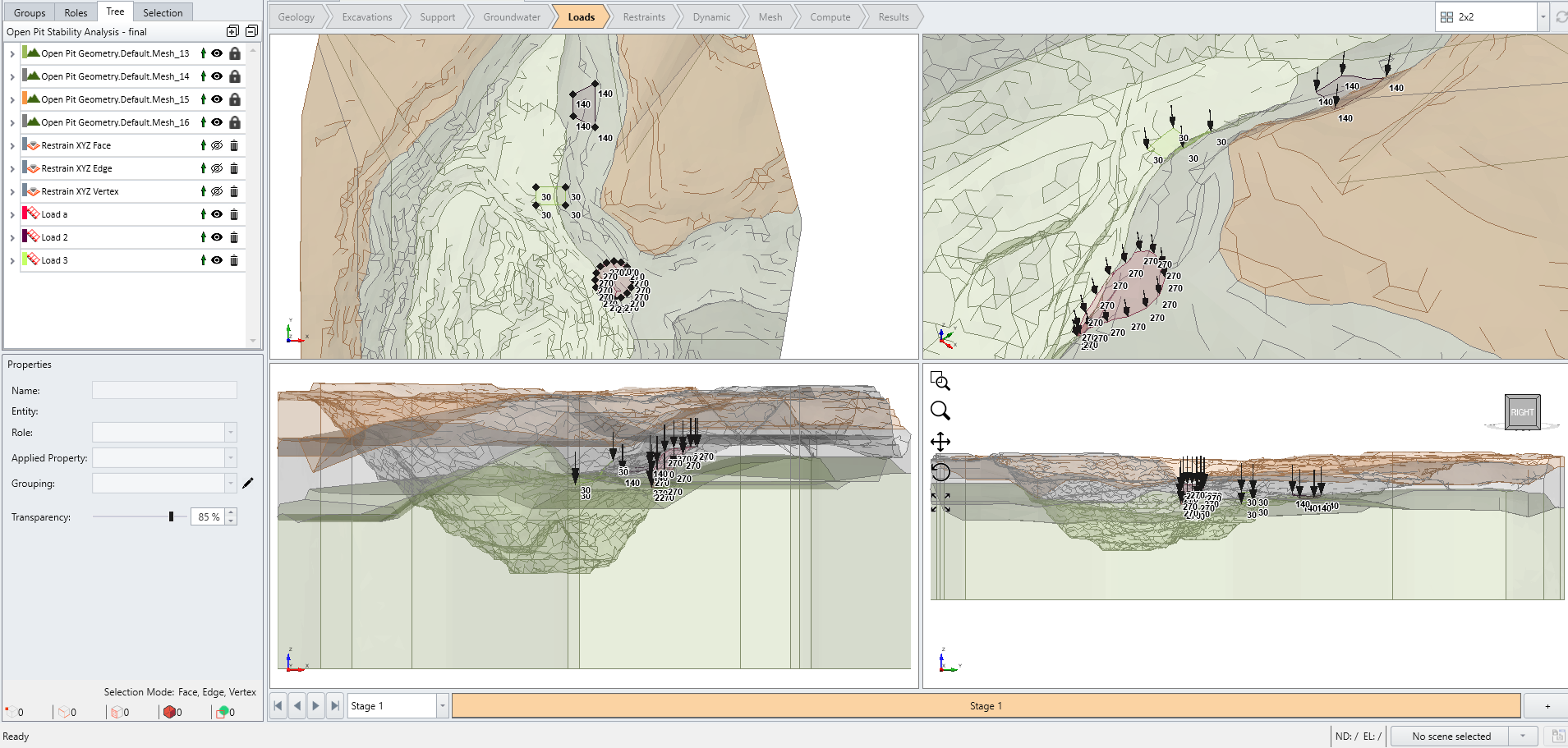
- The figure below shows the model with all three loads added in the model. Each load is named according to the label defined in the dialog.
How to Modify Existing Projected Load Entities
Procedure provided this section is continuation from the last step of How to generate projected load entities Section. It assumes that at least one projected load entity already exists in the model.
- Select Loading > Define Projected Load to visit the Manage Loads dialog.
- Modify the properties saved in samples tagged with “(added)” label.
- After making modifications, check the check boxes of all samples to apply the changes to the projected load entities and click OK.
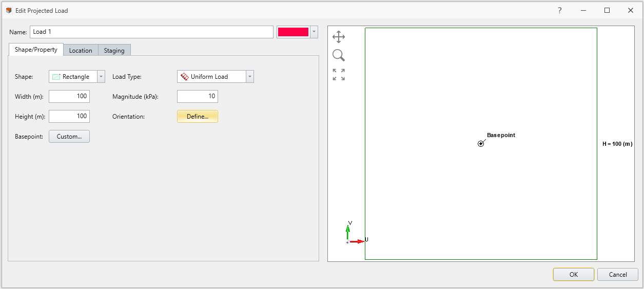
Changes can be made directly to the projected load entities by navigating to pencil icon next to the Applied Property dropdown under properties pane of a projected load entity in Visibility Tree.
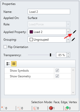
This opens an Edit Projected Load dialog, which have properties saved specific to the selected load entity. The interface remains the same as the one accessed from Define Projected Load, except the Load Property Panel is omitted. Changes made here will update the corresponding load property directly.