Add Restraints/Displacements
Displacement, Restraint, or Free Restraint boundary conditions can be applied to surfaces, edges, or points using the menu/toolbar options or by convenient right-click shortcut, which opens the Add Restraint dialog. These boundary conditions can either be XYZ restraints (zero displacement) or fixed (non-zero) displacements.
To apply restraints or displacements to a face (surface), edge, or point:
- Select the Restraints workflow tab

- Based on the type of boundary on which you are applying the boundary condition, select Faces Selection
 , Edges Selection
  , or Vertices Selection
  as the Selection Mode.
 - Select the face(s), edge(s), or vertice(s) on which to apply the restraint/displacement.
- Select to expand the Add Restraints/Displacements
 sub-menu from the Restraints menu and choose the type of restraint to apply, or to apply the restraint directly from the toolbar (Restrain X, Restrain Y, etc.). In a multi-stage model, displacements may be staged. More information on staging displacements can be found below.
TIP: with the face(s), edge(s), or vertices selected, you can also right-click on the viewing screen and select the restraint type from the Restraints sub-menu.
- When you have selected the type of restraint to be applied, select Apply. The restraint option you selected in Step 4 will be applied to the boundary selected in Step 3. Fixed restraints will be displayed in the viewport as pins, coloured to match the axis of the direction in which it is fixed. Displacements will be displayed in the viewport as arrows with values.
Restrain Type
The Restrain Types available in the Add Restraint dialog in RS3 are:
- Restrain X
- Restrain Y
- Restrain Z
- Restrain XY
- Restrain YZ
- Restrain XZ
- Restrain XYZ
- Free Restraints (Free XYZ)
- Displacements
RESTRAIN X
The Restrain X  option is used to apply zero x-displacement boundary conditions. The nodes will be free to move in the y- and z-directions. The x-displacement will be fixed at zero throughout the analysis.
Nodes restrained in the x-direction are indicated by the "pin" symbol in the x-direction, coloured to match the x-axis (red), when Restraints are displayed.
RESTRAIN Y
The Restrain Y  option is used to apply zero y-displacement boundary conditions. The nodes will be free to move in the x- and z-directions. The y-displacement will be fixed at zero throughout the analysis.
Nodes restrained in the y-direction are indicated by the "pin" symbol in the y-direction, coloured to match the y-axis (green), when Restraints are displayed.
RESTRAIN Z
The Restrain Z  option is used to apply zero z-displacement boundary conditions. The nodes will be free to move in the x- and y-directions. The z-displacement will be fixed at zero throughout the analysis.
Nodes restrained in the z-direction are indicated by the "pin" symbol in the z-direction, coloured to match the z-axis (blue), when Restraints are displayed.
RESTRAIN XY
The Restrain XY  option is used to apply pinned boundary conditions.
The nodes will not be free to move in the x- and y-directions, and will maintain zero displacement throughout the analysis.
Nodes restrained in the x- and y-directions are indicated by two "pin" symbols: a red "pin" in the x-direction and a green "pin" in the y-direction, when Restraints are displayed.
RESTRAIN YZ
The Restrain YZ  option is used to apply pinned boundary conditions.
The nodes will not be free to move in the y- and z-directions, and will maintain zero displacement throughout the analysis.
Nodes restrained in the y- and z-directions are indicated by two "pin" symbols: a green "pin" in the y-direction and a blue "pin" in the z-direction, when Restraints are displayed.
RESTRAIN XZ
The Restrain XZ  option is used to apply pinned boundary conditions.
The nodes will not be free to move in the x- and z-directions, and will maintain zero displacement throughout the analysis.
Nodes restrained in the x- and z-directions are indicated by two "pin" symbols: a red "pin" in the x-direction and a blue "pin" in the z-direction, when Restraints are displayed.
RESTRAIN XYZ
The Restrain XYZ  option is used to apply pinned boundary conditions.
The nodes will not be free to move in the x- , y-, and z-directions, and will maintain zero displacement throughout the analysis.
Nodes restrained in the x-, y-, and z-directions are indicated by three "pin" symbols: a red "pin" in the x-direction, a green "pin" in the y-direction , and a blue "pin" in the z-direction, when Restraints are displayed.
FREE RESTRAINTS (FREE XYZ)
The Free Restraints  option is used to free any nodes that are restrained in the x-, y-, and z-directions. It also is used to ensure that all selected nodes will be free to move in the x-, y-, and z-directions. For example, if you are modeling a surface excavation, in most cases you will need to apply a Free boundary condition to all segments of the external boundary representing the ground surface.
The Free Restraints option can also be used to remove non-zero displacement boundary conditions that have been specified.
No symbol appears at nodes that are Free, since they are completely free to move with no restraints.
DISPLACEMENTS
The Displacements  option is used to specify a non-zero, fixed displacement as a boundary condition for the stress analysis. A non-zero displacement boundary condition is similar to a zero displacement boundary condition. Rather than specifying that the displacement at a node is fixed and equal to zero, it is specified that the displacement at a node is fixed and equal to some non-zero value. The Displacement option can be used for back-analysis scenarios, in which boundary displacements are known, and the resulting stress state is to be determined.
To use this option, in the Add Restraint dialog, select the desired displacement for the x-, y-, and z-directions. The displacement in each direction may be Free, Displaced, or Fixed. A Free displacement will allow nodes to move freely in the specified direction. A Displaced displacement will fix the nodes at the desired value. A Fixed displacement will fix the nodes with a displacement equal to zero, with the nodes not free to move in the specified direction.
STAGING
In a multi-stage model, the Staging options allow you to specify the stage at which the displacements will be installed and the stage at which the displacements will be removed. Displacements can be staged by selecting the Stage Values checkbox. Select the Add Stage  button for each stage, enter the Type of displacement (Free, Displaced, or Fixed) to be used in the x-, y-, and z-directions and the value of the displacement for each stage.
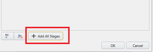
To create all stages at once:
- Go to Restraints > Add Restraints/Displacements
- Click on Displacements
- Check Stage Values box
- Click on "+Add All Stages" button
To change the Displacement type for all stages in specific direction at once, just right click on the header and select the desire option, similar to the image shown bellow:
If you do not stage the displacement on a multi-stage model, then the displacement will be applied with the same value at all stages.
Different stage values for X, Y and Z directions
If necessary, the displacements can be staged independently by selecting the Different stage values for X, Y and Z directions checkbox. If this checkbox is selected, you will be able to specify the Type and Value of the displacement in the x-, y-, and z-directions independently for each stage.
If your displacement is staged, it is a good idea to cycle through the Stage Tabs after adding the displacement boundary condition, to verify that the displacement(s) are applied at the correct stages and that the values are correct. If not, then repeat Steps 1 to 5 (above) or select and edit the displacement using the Properties Pane, and make sure that the correct Type and Values have been applied at the correct stages.