Tunnel Supports
For tunnel designs, supports are added to provide tunnel restraints. In RS3 Tunnel Designer, the Supports can be added to the tunnel after Tunnel Profile, Tunnel Path, and Tunnel Excavations are defined. Three types of supports can be added to the tunnel: bolts, liners, and beams.
Steps to add loads:
- Make sure the Profile, Path, and Excavation are specified for the design.
- Select the Add Supports
 button in the top middle of the Tunnel Designer dialog. Alternatively, select a tunnel design from the tree, click the “…” icon to its right, and select Add Supports from the dropdown list. A Support item will appear under the tunnel design.
 - Select the Supports item, click the “..” icon to its right, and select a support type to add from the dropdown menu.
- Add Bolts on Face
- Add Bolts on Perimeter
- Add Liner on Face
- Add Liner on Perimeter
- Add Beams on Perimeter
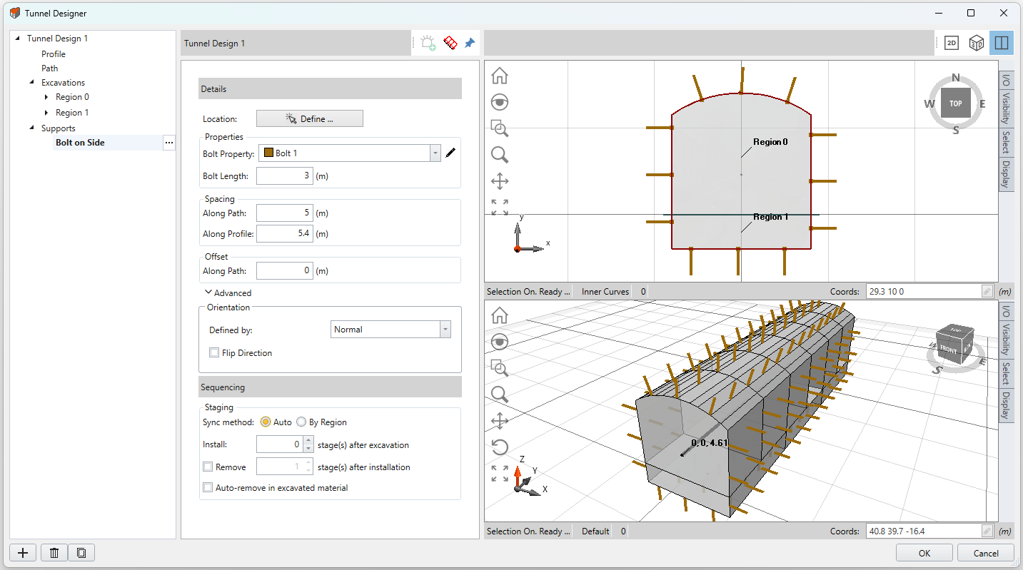
- Select a support item to set properties (see image below). The support location, type, distribution, sequencing, and orientation can be customized, as described in detail below.
For more information on supports, see the RS3 Liners, Bolts, and Beams topics.
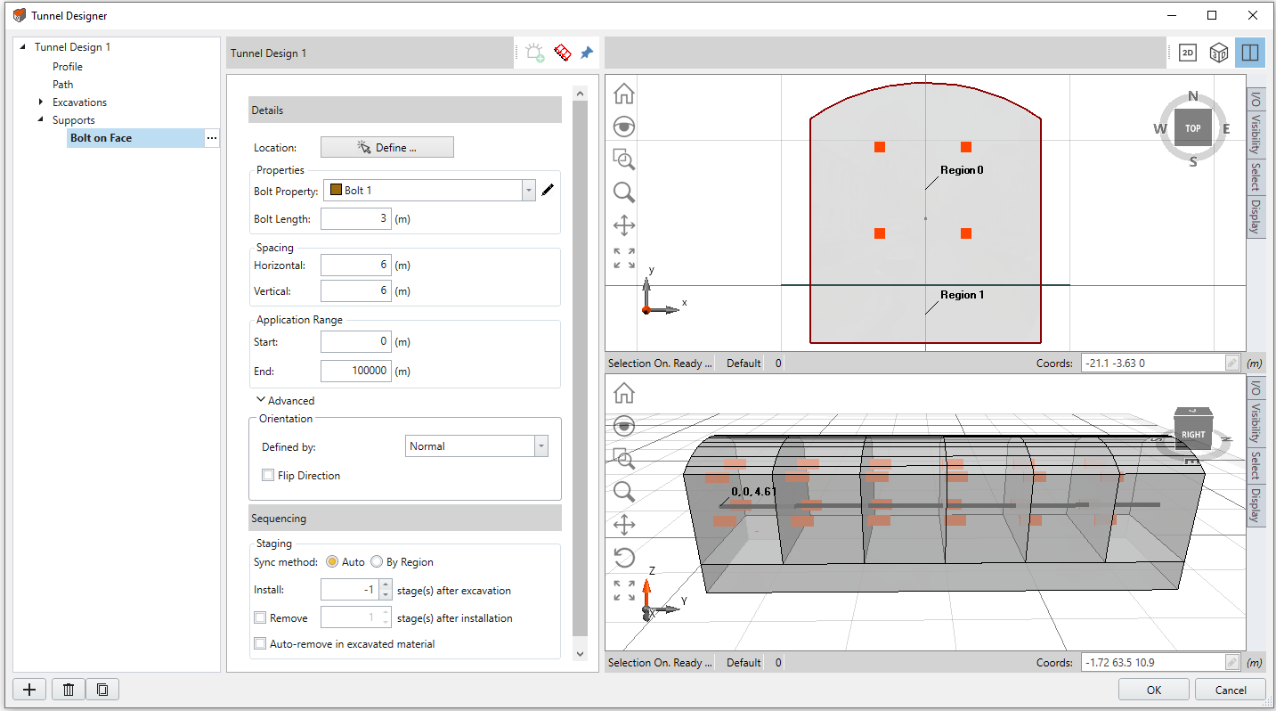
Bolt on Face
To define the bolt Location, select the Define button  . In the 2D viewport, use the mouse to select a region, hit enter. Then use the point tool to click or enter a location within the region. Hit enter to finish. The bolt will be applied to the tunnel face.
Choose the Bolt Property and define the Bolt Length. To modify bolt properties, select the edit tool  beside. By default, the bolt set are applied as a uniform pattern. The pattern Spacing in horizontal and vertical directions can be defined. The Start and End of the Application Range can be modified, which the support will be applied within the range measured along the path.
Bolt on Side
To define the bolt Location, select the Define button . In the 2D viewport, use the mouse to select at least three to four points along the curve, that the bolts will be applied to, or enter coordinates alternatively. Hit enter to finish. The bolt will be applied to the tunnel sides.
Choose the Bolt Property and define the Bolt Length. To modify bolt properties, select the edit tool beside. By default, the bolt set are applied as a uniform pattern around the sides. The pattern Spacing in directions along path and along profile can be defined. To Offset the bolts along path, enter an offset value. The start point is the center point.
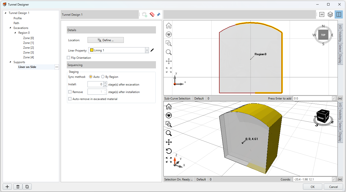
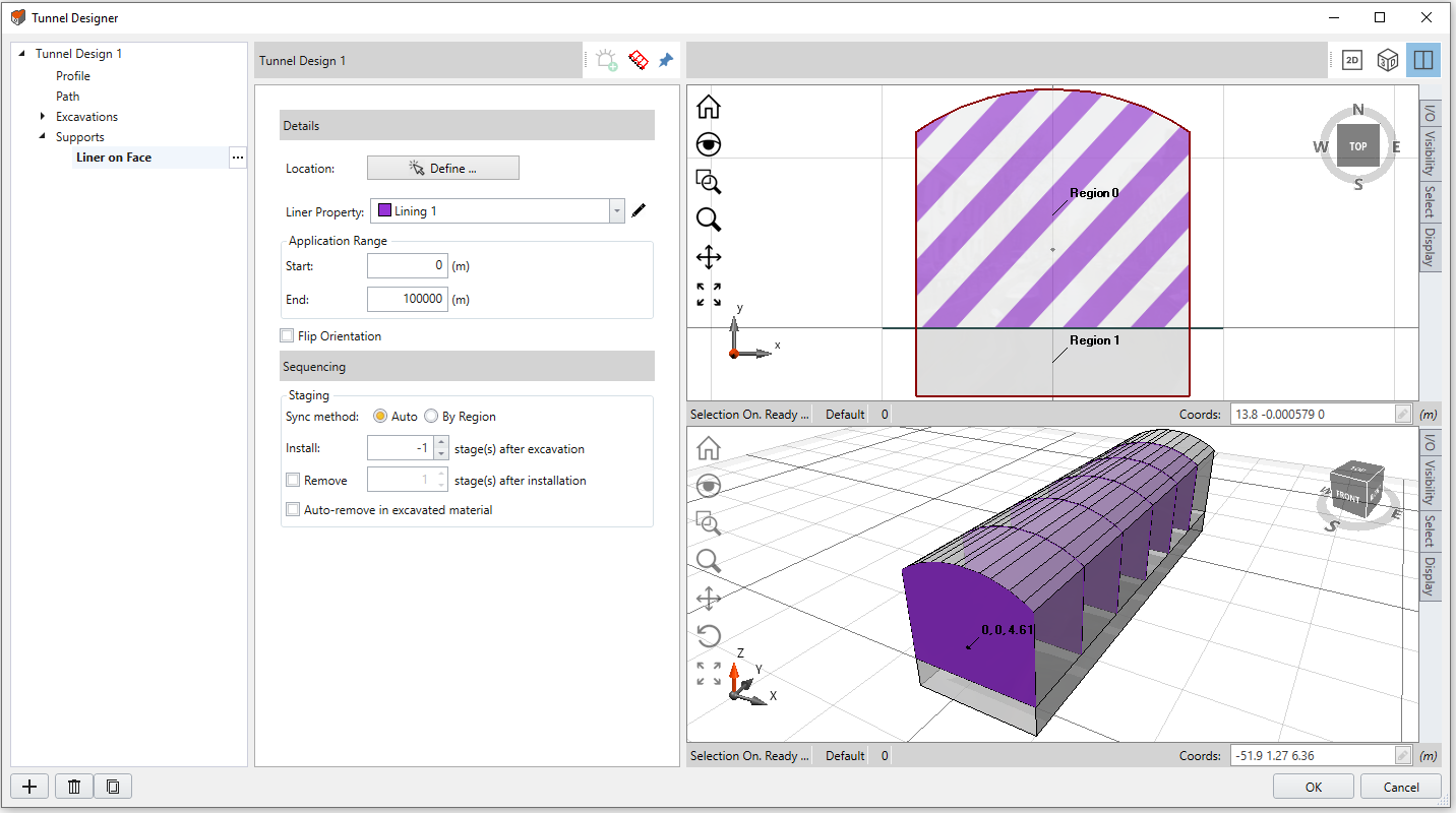
Liner on Face
To define the liner Location, select the Define button . In the 2D viewport, use the mouse to select a region, hit enter. The liner will be applied to the tunnel face.
Liner Property
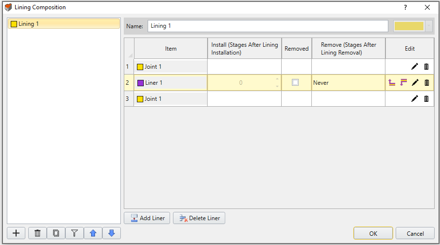
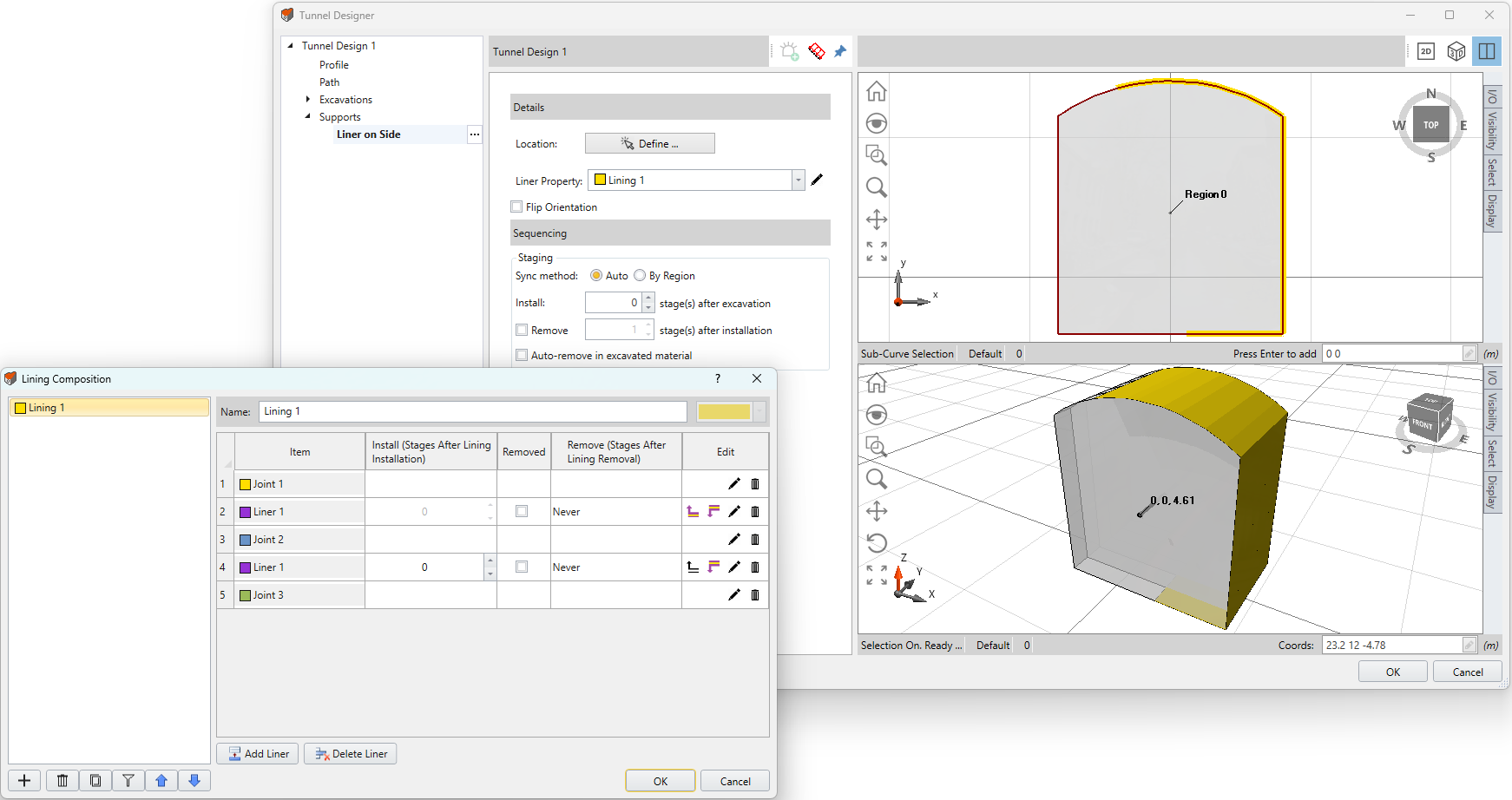
Choose the Liner Property from the dropdown menu. The liner can be a single layer of liner, or a set of multiple liners including joint interfaces. You can modify the Lining Composition with the edit tool beside the Liner Property list.
A Lining Composition dialog will display as shown below. In this dialog, you can create a liner set with the add  button. Within a liner set, you can add
  or delete
  a liner layer. For each liner layer, you can add a joint layer above
  or below
  , edit joint properties , delete a joint layer
  , and set the install and remove stage for each layer if needed.
To view the liner composition visually in the model, see the Display Liner Compositions section on this page.
Application Range
The Start and End of the Application Range can be modified, which the support will be applied within the range measured along the path.
Flip Direction
In RS3, the term liner refers to a collection of lining layers that can include joint interfaces. The Flip Direction option allows you to flip the order of liner layers defined in lining composition dialog. For more information, see the Flip Direction section under RS3 Add Lining topic.
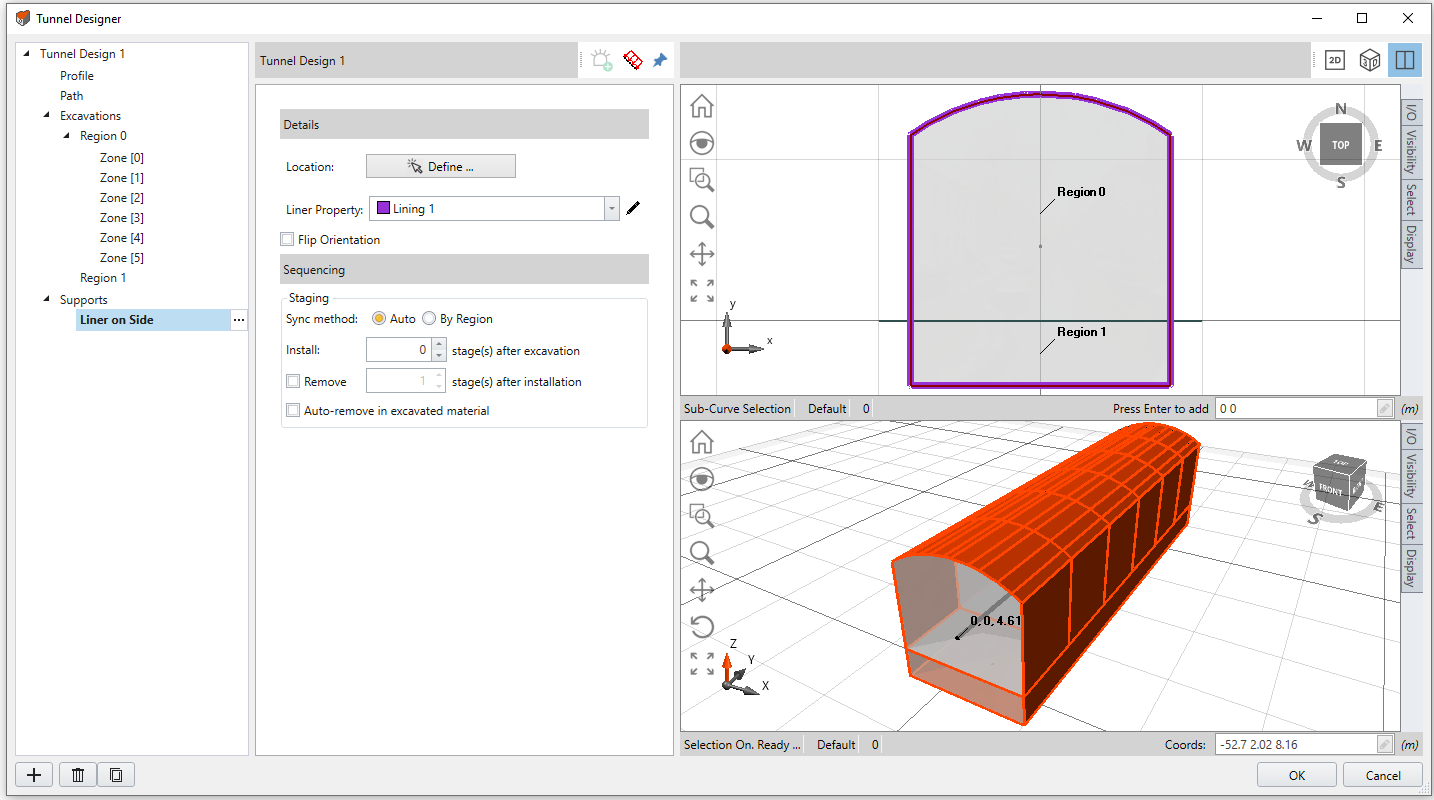
Liner on Side
To define the Liner Location, select the Define button. In the 2D viewport, use the mouse to select at least three to four points along the curve, that the liner will be applied to, or enter coordinates alternatively. Hit enter to finish. The liner will be applied to the tunnel sides.
Liner Property
Choose the Liner Property from the dropdown menu. The liner can be a single layer of liner, or a set of multiple liners including joint interfaces. You can modify the Lining Composition with the edit tool beside the Liner Property list.
A Lining Composition dialog will display as shown below. In this dialog, you can create a liner set with the add button. Within a liner set, you can add or delete a liner layer. For each liner layer, you can add a joint layer above or below , edit joint properties , delete a joint layer , and set the install and remove stage for each layer if needed.
To edit the Liner and Joint properties, exit the Tunnel Designer dialog (with the OK button) and proceed to the Define Liner Properties and Define Joint Properties option respectively, under the Liners sub-menu under the Support menu.
To view the liner composition visually in the model, see the Display Liner Compositions section on this page.
Flip Direction
In RS3, the term liner refers to a collection of lining layers that can include joint interfaces. The Flip Direction option allows you to flip the order of liner layers defined in lining composition dialog. For more information, see the Flip Direction section under RS3 Add Lining topic.
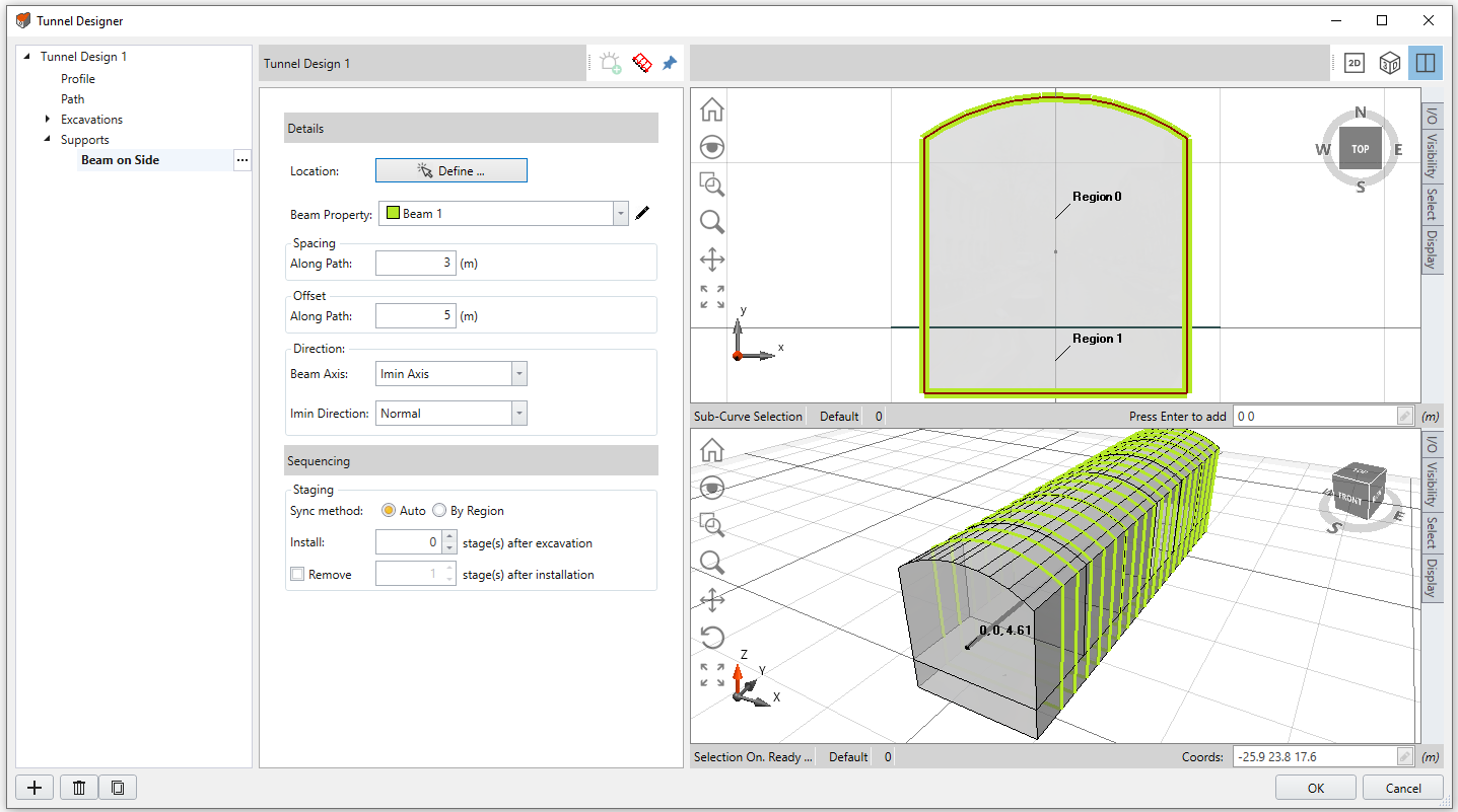
Beam on Side
To define the beam Location, select the Define button . In the 2D viewport, use the mouse to select at least three to four points along the curve, that the beam will be applied to, or enter coordinates alternatively. Hit enter to finish. The beam will be applied to the sides along path.
Choose the Beam Property from the dropdown menu. To modify beam properties, select the edit tool beside. By default, the beams are added along the path with a 3m spacing. The Spacing can be user-defined. To Offset the beams along path, enter an offset value. The start point is the center point.
Beam Direction
The Beam Direction section define how beams are installed on a boundary with respect to the beam cross-section. You may choose either the Imin Axis or the Imax Axis of the beam cross-section to represent the beam cross-sectional axis.
Imin / Imax Direction
You must then choose a direction for the chosen beam axis. The following options are available:
- Normal
- Trend & Plunge - See the help page Sign Convention - Trend/Plunge for trend/plunge sign convention in RS3.
- Vector
Advanced
The Advanced section is available for bolt supports.
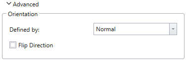
Expand the section to define the support orientation with available methods:
- Vector
specify a vector with XYZ components. The normalized vector will be shown below in blue text. - Trend/Plunge
specify a trend angle and a plunge angle. See the help page Sign Convention - Trend/Plunge for trend/plunge sign convention in RS3. - Normal
The support will be normal to the selected face or perimeter. - Local +x
The support will be pointing to the local positive x axis direction. - Local +y
The support will be pointing to the local positive y axis direction. - Local +z
The support will be pointing to the local positive z axis direction.
The Flip Direction option is available for Normal, Local +x, Local +y, and Local +z methods. When it is enabled, the support is installed facing the opposite direction.
By default, the support orientation is Normal to the face/perimeter, and Flip Direction unchecked.
Sequencing
The tunnel support is primarily used to support the tunnel after excavation – to prevent the tunnel from falling. Thus, the tunnel support is corelated to excavation staging. To account for this characteristic, the Sequencing section is designed to synchronize the tunnel support with excavation staging of a region.
To stage a tunnel support:
- Select a region for the support to synchronize with. With the Auto option, the tunnel support will be synchronized with its region. With the By Region option, you can select a region from the dropdown list.
- Specify the timing to install a support with the Install: # stage(s) after excavation. The installation stage is correspondent to the excavation stage of the REGION.
- Select the checkbox to enable the Remove # stage(s) after installation option, and you can specify the duration of the support in the unit of stages. If this option is disabled, the support will be kept till the last stage.
The Auto-remove in excavated material option is available for bolts and liner supports. If the option is enabled, when the zone is excavated, the support of the zone will be automatically removed as well. Note that this option has a higher priority and will replace the Remove # stage(s) after installation option.
See the RS3 Tutorial – Sequence Tunnel Design for an example on Tunnel Design with supports.
Display Liner Compositions
In RS3 Tunnel Designer dialog, only the top layer of a lining set will be displayed in the viewport. For example, in Image 1 below, the top layer of the lining set is Joint 1 with color yellow. Therefore, the lining is colored yellow in the viewport.
In RS3 modeller viewport, the full lining composition can be displayed with following steps:
- Make sure the geometry must be divided with the Divide All Geometry or Constrained Divide All option.
- Select a Lining entity from the Visibility Tree. Hide other entities (select Hide All But Selected Geometry option from the View menu).
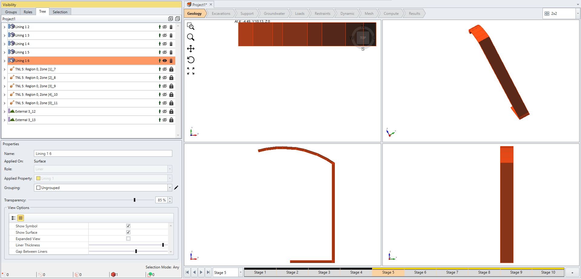
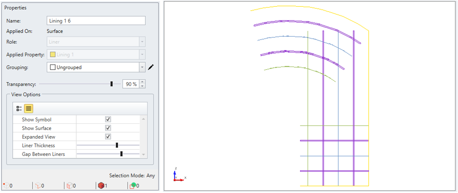
Image 2. Lining Composition in RS3 modeller (a) - Under the Properties panel select the checkbox for Expanded View.
- Adjust the slide bar for Liner Thickness and Gap Between Liners to customize the liner layer view.
- Now all layers within the lining set will be displayed. As seen in Image 3 below, the full lining composition defined in Image 1 is shown.