Import RS2 Project
RS2 project can be imported in RS3 using the import RS2 project.
Select: File > Import > Import RS2 project ![]()
You will be prompted with files to choose. The supported import file extensions are:
- RS2 Model files (*.fea;*.fez,*.zip),
- RS2 Feture file (*.fea)
- RS2 Zipped Files (*.fez)
- Zip Files (*.zip)
When you import a RS2 file, RS2 import wizard will guide you through the import process. Below shows an example of importing RS2 introduction tutorial: 'Materials and staging'.fez.
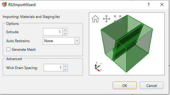
The three options are available when importing RS2 project:
- Extrude: allows you to define the extrusion width of the model (in y-axis)
- Auto restraints: applies restraints for extruded model. Three options are available (Underground, Surface, Rotation (Surface)
- Generate Mesh: By selecting on this, you can generate Mesh as you import the RS2 proejct.
Under advanced setting, you can also define the spacing of wick drains along the extruded axis. This is applied when there is wick drain in RS2 model.
Select OK and you will be given a message with import information as shown below:
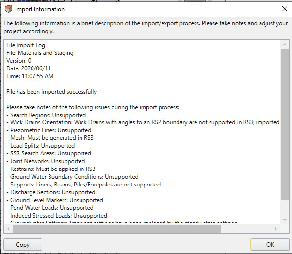
The message lists the completion of import along with important messages during the import process.
Below are the list of items that can be imported from RS2 to RS3:
Supported feature
- All the project settings
- All bolt and material properties
- Wick Drains *
- Bolts
- Loads (distribution and line)
- All boundaries **
- Field Stress
Unsupported feature:
- Mesh must be generated in RS3
- Retrains must be generated in RS2
- Load splits
- SSR Search Areas
- Joint Networks
- Liners
- Discharge Sections
- Ground Level Marker
- Pond Water Loads
Conversion of RS2 field stress to RS3 field stress
Sigma 1 (RS3) = Sigma 1 (RS2)
Sigma 2 (RS3) = Sigma Z (RS2)
Sigma 3 (RS3) = Sigma 3 (RS2)
Orientation (RS3) = Trend/Plunge
Sigma 1 Trend = same
Sigma 1 Plunge = Sigma1 – Angle (RS2)
Sigma 3 Trend = same
Sigma 3 Plunge = Angle (RS2)
Gravitational field stress of RS2 to RS3
Use actual ground surface (same for RS2 and RS3)
Use effective stress ratio (same for RS2 and RS3)
Case where Use variable stress ratio = same
K1 (RS3) = Effective Stress Ratio in plane (RS2)
Locked in Horizontal stress 1 (RS3) = Locked horizontal stress in plane (RS2)
K2 (RS3) = Effective Sress Ratio out of plane (RS2)
Locked in Horizontal stress 2 (RS3) = Locked horizontal stress out of plane (RS2)
Case where Use variable stress ratio = Same
a,b,c for horizontal stress 1 (RS3) are the same as the in plane a,b,c (RS2)
a,b,c for horizontal stress 2 (RS3) are the same as the out of plane a,b,c (RS2)
Orientation (RS3)
Defined by: Same
Trend: same