Uniform Load
Uniform loads can be applied to boundaries (faces, edges, or vertices) with the Define Projected Load option and/or Add Loads to Selected option and specifying Uniform Load as the Load Type. Using both options, a load can be applied over a defined surface area; however, load application on edges and vertices are only available through Add Loads to Selected option.
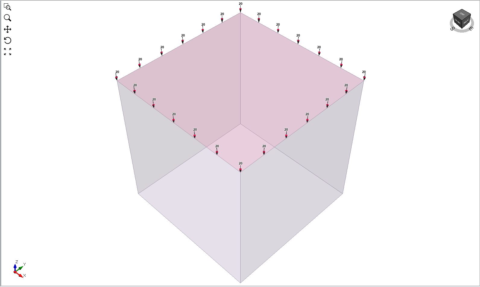
To apply a Uniform Load to a face:
- Select the Loads workflow tab

- Select Faces Selection
 as the Selection Mode.
 - Select the face(s) on which to apply the load.
- Select Add Loads to Selected
 from the toolbar or the Loading menu.
 - You will see the Add Load to Selected dialog. In this dialog:
- Select the Load Type = Uniform Load.
- Enter the load Magnitude and specify the load Orientation (e.g. Normal, Local +x, Local +y, Local +z, Vector (x,y,z), or Trend/Plunge)
- In a multi-stage mode, the Staging options allow you to specify the stage at which the load will be installed and the stage at which the load will be removed. Uniform loads can be staged by selecting the Stage Factors checkbox, and entering a Magnitude Factor for the load magnitude at each stage. If you do not stage the load on a multi-stage model, then the load will be applied with the same magnitude at all stages.
See below for details about the load magnitude, orientation, and staging.
- When finished specifying the load properties and the preview of the applied load, as indicated by the display of green arrows, is as desired, select Apply. The Uniform Load will be applied to the selected face(s), as indicated by the display of red arrows and the magnitude.
- Check the direction of the arrows and the magnitude, to make sure that this is the load you wished to apply. If there is a mistake, you can repeat the above steps to apply the correct load, or select and edit the load using the Properties pane to change the load parameters.
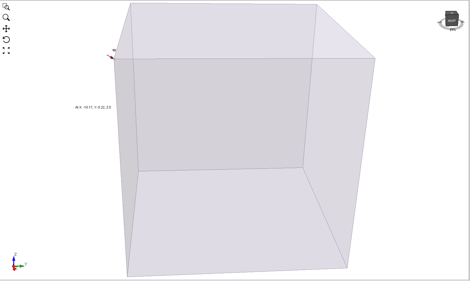
 or Vertices Selection
  to select the edge(s) or vertices, respectively, on which to apply the load.
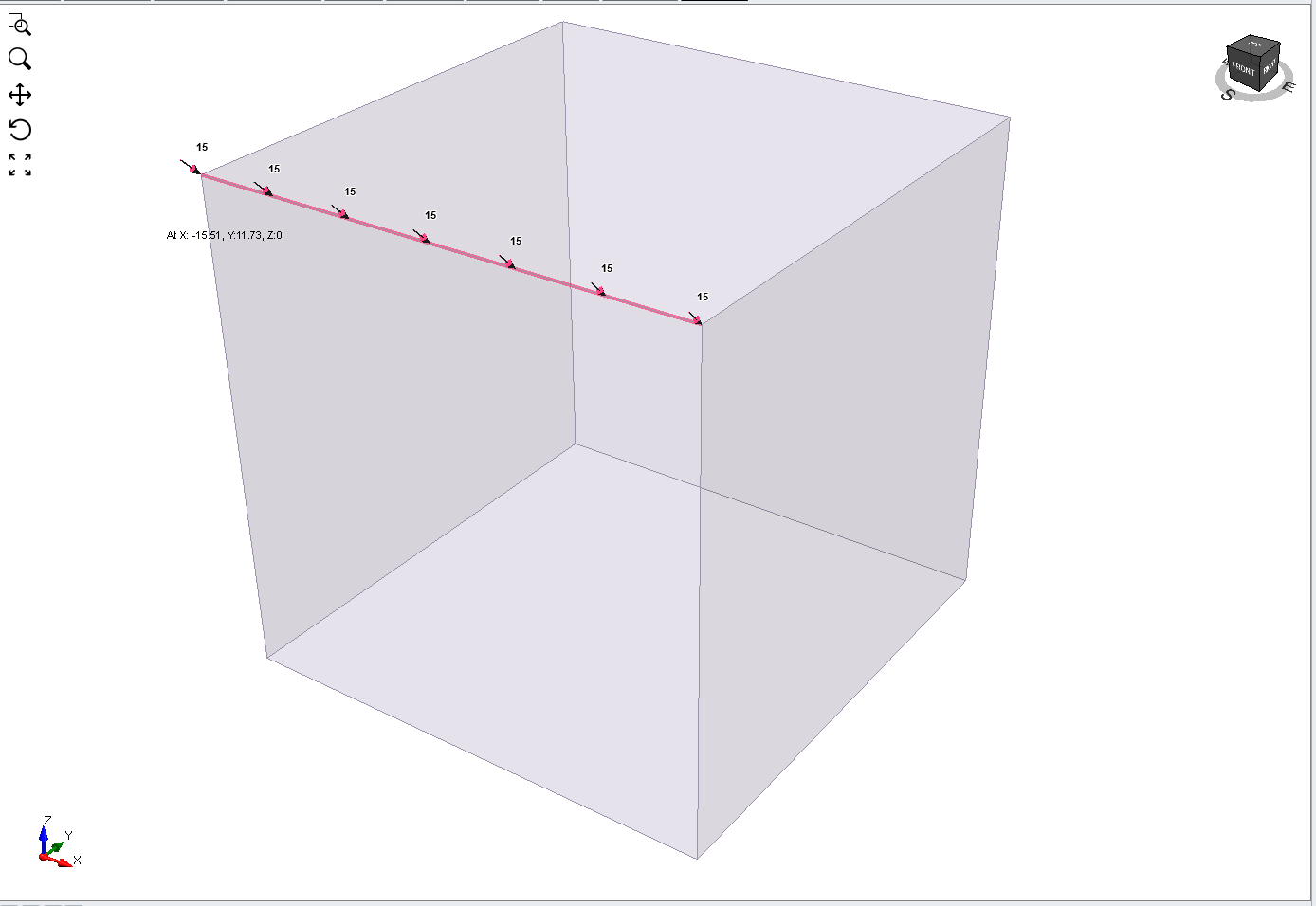
LOAD MAGNITUDE
A distributed load magnitude is generally entered as a positive value. The direction of load application is specified by selecting an appropriate Orientation method (see below) in the Add Loadto Selected dialog. If a negative load magnitude is entered, the direction of the applied load will be reversed.
LOAD ORIENTATION
The load Orientation may be specified using one of the following options:
- Normal - loads are applied normal to the boundaries
- Local +x - loads are applied to the boundaries in the positive x-direction (i.e. +x)
- Local +y - loads are applied to the boundaries in the positive y-direction (i.e. +y)
- Local +z - loads are applied to the boundaries in the positive z-direction (i.e. +z)
- Vector (x,y,z) - specify a vector from the x, y, and z-directions
- Trend/Plunge - specify a trend and plunge (see Sign Convention for more information)
Flip Orientation
Note that after adding a load, the orientation may sometimes be opposite from the intended direction (i.e. 180 degrees off). If this occurs, you can select the load and use the Properties pane option to "flip" (i.e. reverse) the load orientation by 180 degrees.
STAGING DISTRIBUTED LOADS
On a multi-stage model, distributed loads can easily be staged by selecting the Stage Factors checkbox in the Add Load to Selected dialog (Step 5 above). You will see Stage Magnitude Factors in the expanded dialog. Select the Add Stage  button for each stage and enter a Magnitude Factor for the load at each stage. The Magnitude Factor is multiplied by the load magnitude to obtain the actual load magnitude used at each stage (e.g. if the Magnitude Factor = 0.2 and the load magnitude = 5, then the actual load magnitude applied at that stage will be 0.2 * 5.0 = 1.0). This allows you to increase or decrease the applied Uniform distributed load applied at any stage. NOTE:
- Magnitude Factor = 1 means that the load magnitude will be equal to the magnitude(s) entered in the Add Load to Selected dialog.
- You can increase or decrease the load at any stage, by entering a Magnitude Factor greater than or less than 1 (e.g. a Magnitude Factor = 2 would double the load magnitude).
- You can remove the load at any stage, by entering a Magnitude Factor = 0. The load will not exist in any stage in which the Magnitude Factor = 0, and will not appear on the model.
If your load is staged, it is a good idea to select the Stage Tabs, after adding the load, to check that the load is applied at the correct stages, and that the magnitudes are correct. If not, then repeat Steps 1 to 7 (above) or select and edit the load using the Properties Pane, and make sure that the correct Magnitude Factors have been applied at the correct stages.