Tunnel Profile
For tunnel design, the tunnel profile should be first defined. It is the tunnel cross-section and can be created by several methods including tunnel shapes, draw, data tables, and import files, as described in detail below. The tunnel position can be modified with the 3D Placement correspondent to the Reference Point. The tunnel cross-section can be divided into regions with draw tools (e.g. polyline), when no division needed, it will be treated as a whole region (i.e. Region 0).
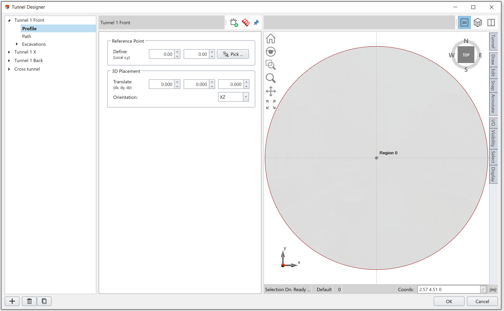
The Profile section is under the Tunnel Design list in the left side of Tunnel Designer dialog. An example tunnel profile is shown below:
Tunnel Outer
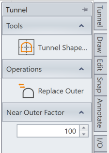
After a tunnel profile is created, by default, it will be defined as the tunnel outer contour, which will be highlighted in dark red. If you would like to re-define your outer, use the Replace Outer option under the Tunnel section from the Toolbar. See the Toolbar – Replace Outer topic for more detail.
Tunnel Profile Methods
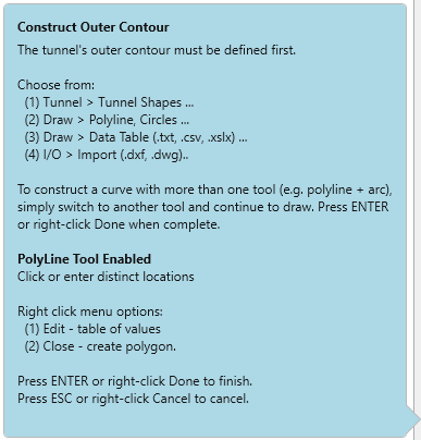
In the Tunnel Designer dialog, when hovering the cursor over the viewport, a note will be displayed for tips on constructing the tunnel cross-section (outer contour). Four methods are available to create a tunnel profile: Tunnel Shapes, Draw, Data Table, and Import. Each method is detailed explained below.
Tunnel Shapes
You can use and modify the pre-defined tunnel shapes provided in RS3 with the Tunnel Shapes option. Steps are followed:
- Select Tunnel from the toolbar in the right of dialog.
- Select Tunnel Shapes. You will be prompted to a dialog.
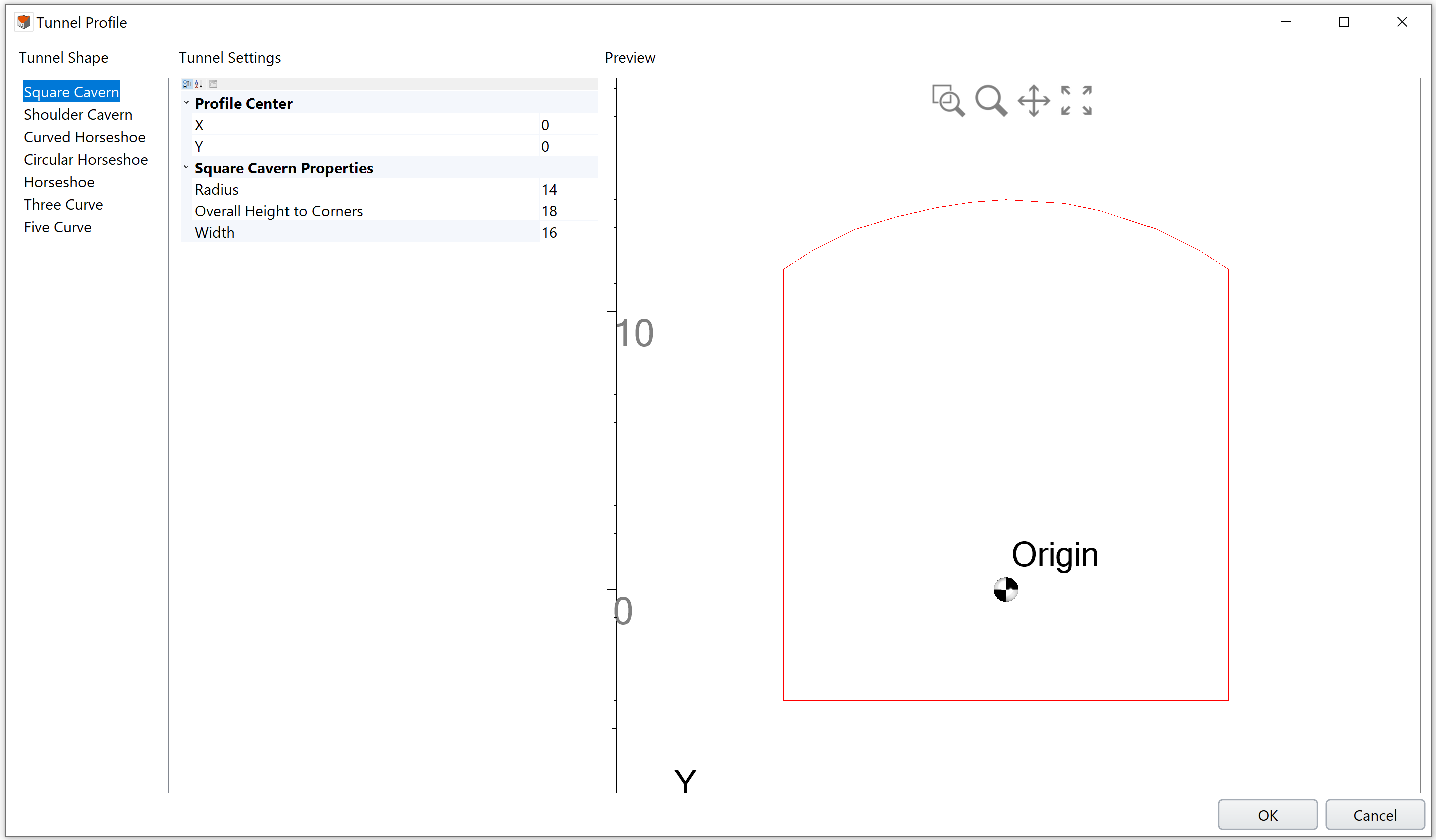
- In the Tunnel Shapes dialog, select a pre-defined shape and define the settings. See Tunnel Shapes topic for more detail.
- Click OK to complete. The profile will be shown in the Tunnel Designer viewport.
Draw
You can manually draw the profile outline using the Draw options. Steps are followed:
- Select Draw from the toolbar in the right of dialog.
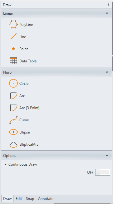
- Under the Draw bar, you can manually draw your tunnel cross-section using provided drawing options, including polyline, line, point, data table (with x and y coordinates), curve, and etc.
See the Toolbar - Draw topic for more details.
Data Tables
You can define the tunnel cross section using a Data Table with input x and y coordinates. Steps are followed:
- Select Draw from the toolbar in the right of dialog.
- Select Data Table. You will be prompted to a dialog.
- In the Edit Point dialog, input x and y coordinates in the spreadsheet cells starting from the top left cell (A1). You can also import a file of data points to the spreadsheet.
- Click OK to apply. The tunnel profile will be shown in the viewport.
See the Toolbar - Draw topic for more details.
Import
You can import any tunnel profile that is saved with the *.dxf or *.dwg extension with I/O option. Steps are followed:
- Select I/O from the toolbar in the right of dialog.
- Select Import.
- Open a file with tunnel profile to import. Supported file formats are *dxf or *.dwg.
- Click Open to apply. The tunnel profile will be shown in the viewport.
See the Toolbar - I/O option for more details.
After the tunnel profile is created, you can use the drawing tools and options to Edit the profile, or customize the view (Annotate, I/O, Visibility, Select, Display).
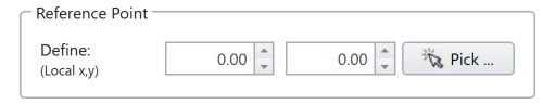
Reference Point
The Reference Point is used to refer the location of the whole profile, when moving the profile, or specifying the path. Input the local x and y coordinates of your Reference Point, or select the “Pick” button and define a point with your mouse in the viewport. By default, the reference point is the tunnel center. The Reference Point will be marked in 2D and 3D view.
There are three uses of the Reference Point: defining the tunnel’s local 3D Placement, define the tunnel path, and position the tunnel in the model. Each is described below.
- Local 3D Placement
Under the 3D Placement section, you can define the location and orientation of your tunnel profile. The profile will be translated or rotated based on the Reference Point. See the 3D Placement section below for more details. - Tunnel Path
The Reference Point refers the profile (2D) relative to the path (third dimension). If the tunnel path is defined with Extrude method, the start point of the extrusion is the Reference Point on the surface (profile). For other tunnel path methods (Coordinates or Import), the coordinates of the first point for the path will dominate over the Reference Point. - Tunnel Position in the Model
A tunnel can be added to the model with the Add a Tunnel option. In the Add Tunnel dialog, you can adjust the tunnel position in the global coordinate system. The adjustment will be based on the Reference Point.
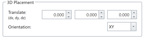
3D Placement
Specify the location and orientation of your tunnel in the 3D viewport. The location of the tunnel can be specified by applying a translational vector (dx, dy, dz) with respect to the Reference Point in 3D view.
To specify the tunnel Orientation, use the options from the dropdown list. With Orientation = XY, XZ, or YZ options, the tunnel cross-section will be placed in the correspondent plane, and it will extrude in the third direction. With Orientation = Trend/Plunge, specify a trend angle and a plunge angle to change the tunnel orientation. The reference axis is the reference point along the tunnel direction.
Right Click Shortcut
Right click the tunnel model in 2D viewport, shortcut options are listed, including edit, undo, redo, cut, copy, paste, and delete the selected model. See the Edit section in Toolbar topic for details.
Deleting A Boundary
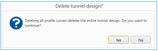
When there is only one boundary defined, deleting the boundary with right-click and Delete option will delete the entire tunnel design. A warning message will display as below.
When there are multiple boundaries defined, deleting the outer contour is not allowed. An error message will display as shown.
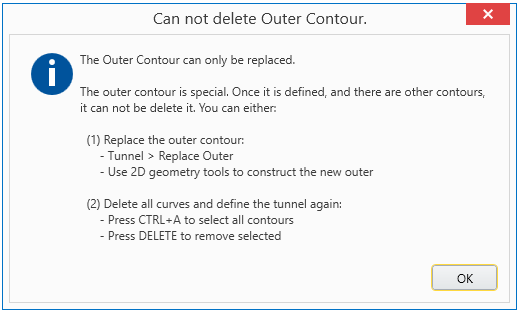
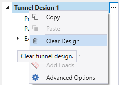
You can either use Clear Design option with the Tunnel Design “…” button (see below), or re-define an outer with the Replace Outer option under the Tunnel tool from Toolbar.