Define Joint Properties
A Liner Interface as defined is a sliding joint in RS3 (see the Liner Interface Overview topic for more details). Thus, liner interface properties are defined with the Define Joint Properties option by following steps:
- Select the Support workflow tab

- Select Define Joint Properties
 from the toolbar or select: Support > Liners > Define Joint Properties from the drop-down menu.
TIP: You can also right-click on the viewing window and select Define Joint Properties from the menu.
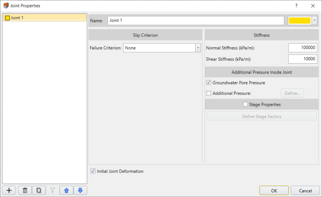
- You will see the Joint Properties dialog with a list of currently defined joints at the left of the dialog.
- To create a joint, select the Add
 button, or choose an existing joint from the list at the left of the dialog.
 - Under Slip Criterion section, choose a failure criterion and enter the required input parameters. There are five different joint types to choose from:
Slip Criterion
Slip Criterion = None
If the slip criterion is selected as none, then joints will behave elastically, according to the normal and shear joint stiffness. Plastic slip cannot occur.
The Mohr-Coulomb, Barton-Bandis, Geosynthetic Hyperbolic and Material Dependent models are described below. If Slip Criterion is set to one of these models then local joint slip can occur if the shear stress on a joint element exceeds the shear strength as defined by the Slip Criterion parameters.
Slip Criterion = Mohr-Coulomb
The Mohr-Coulomb Slip Criterion parameters are:
- Cohesion
- Friction Angle
- Tensile Strength
Residual Strength
If you select the Residual Strength checkbox for the Mohr-Coulomb criterion, you can define residual values of tensile strength, cohesion and friction angle. The residual strength parameters will be in effect if a joint slip or tensile failure occurs (i.e. peak strength envelope has been exceeded).
Check Mohr-Coulomb failure criterion for more details on the perimeters.
Slip Criterion = Barton-Bandis
The Barton-Bandis Slip Criterion parameters are:
- JCS
- JRC
- Residual Friction Angle
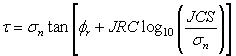
The original Barton equation for the shear strength of a rock joint is given by Eqn.1
where is the basic friction angle of the failure surface, JRC is the joint roughness coefficient, and JCS is the joint wall compressive strength [Barton, 1973, 1976]. On the basis of direct shear test results for 130 samples of variably weathered rock joints, this was later revised to Eqn.2:
where  is the residual friction angle of the failure surface [Barton and Choubey, 1977]. Barton and Choubey suggest that can be estimated from Eqn. 3:
where r is the Schmidt hammer rebound number on wet and weathered fracture surfaces and R is the Schmidt rebound number on dry unweathered sawn surfaces. Equations 2 and 3 have become part of the Barton-Bandis criterion for rock joint strength and deformability [Barton and Bandis, 1990].
For further information on the shear strength of discontinuities, including a discussion of the Barton-Bandis failure criterion parameters, see Practical Rock Engineering (Chapter 4: Shear Strength of Discontinuities) on the Rocscience website.
Residual Strength
If you select the Residual Strength checkbox for the Barton-Bandis criterion, the residual strength will be given by:
(i.e. if a joint slip occurs, the JRC and JCS component of the joint shear strength will be set to zero and the shear strength will depend only on the residual friction angle and the normal stress).
Slip Criterion = Geosynthetic Hyperbolic
The Geosynthetic Hyperbolic slip criterion can be used for modelling the shear strength of the interface between a geosynthetic (e.g. geotextile or geogrid) and soil.
The Geosynthetic Hyperbolic slip criterion is defined by the following equation:
This equation was derived from a study of the constitutive behaviour of geosynthetic interfaces [ Esterhuizen, Filz & Duncan (2001) ], and has been found to characterize the shear strength of soil / geosynthetic interfaces and other types of interfaces. Note the definition of the adhesion and friction angle parameters:
- Adhesion
 is defined as the shear strength at
  (i.e. the Adhesion for a Hyperbolic shear strength envelope is actually the limiting, maximum shear strength, for high normal stress).
 - Friction angle
 is defined as the friction angle at is defined at
  .
.
The following figure illustrates a hyperbolic shear strength envelope.
In addition to the peak values of Adhesion and Friction Angle, you may also define residual values of Adhesion and Friction Angle. The residual values will be used in the analysis if the peak strength has been reached. If you do not wish to consider residual strength, then enter zero for these parameters.
Slip Criterion = Material Dependent
If the Joint Slip Criterion = Material Dependent, then the joint strength (and optional stiffness) will be derived from the soil or rock materials through which the joint passes. The Material Dependent option is applicable if the soil or rock materials use the Mohr-Coulomb or Hoek-Brown strength options. It is not applicable for the Cam Clay strength options.
The material-dependent joint strength is defined in terms of an Interface Coefficient which is used as a multiplier for the cohesion and friction angle of the surrounding material. The Interface Coefficient ( Ci) is applied as follows to determine the joint cohesion and friction angle from the material cohesion and friction angle:
Cjoint = Ci * Csoil
Phi = ArcTan (tan(Phisoil)* Ci)
Residual joint strength parameters are similarly determined from the residual soil/rock strength parameters if the surrounding material has failed. For Hoek-Brown materials, equivalent values of cohesion and friction angle are first determined, and then the interface coefficient is applied to determine joint strength.
Normal & Shear Joint Stiffness
Each joint element has a normal and a shear spring stiffness which relates the normal and shear stress on the element to the normal and shear displacement.
Joint stiffness is usually not a well-known parameter. Methods of estimating joint stiffness have been derived, see the Estimating Joint Stiffness topic for two possible methods (one method is based on the properties of the joint infilling material, the other is based on the deformation properties of the rock mass and the intact rock).
Material Dependent Joint Stiffness
If the Joint Slip Criterion = Material Dependent (see above for description) then the joint stiffness (and strength) can be defined with respect to the surrounding material properties, using a multiplying coefficient. The Material Dependent joint stiffness coefficient is optional and can be defined by selecting the Material Dependent Stiffness option and entering a Stiffness Coefficient (Cs).
RS2 uses a zero thickness joint element thus in order to maintain numerical stability and realistic behaviour, the stiffness coefficient is applied as follows to determine the normal and shear joint stiffness based on the material modulus:
Ks = Cs * Young's Modulus soil;
Kn = 10 * Ks
These values were found adequate for most applications; however, material-dependent joint stiffness is optional, and the user can input the stiffness values manually if required.
Initial Joint Deformation
Initial Joint Deformation refers to how the joint behaves in regard to the far-field stresses.
- If the Initial Joint Deformation is ON, then the joint will deform based on both the far-field stresses and the induced stresses due to any excavations. As a result, the stress field in the vicinity of the joint will be altered from the initial far-field distribution. This will be evident if you run an analysis with a joint only (i.e. no excavations).
- If Initial Joint Deformation is OFF, then a single joint, with no excavation, has no effect at all (try running this). With no Initial Joint Deformation, only the induced stresses from the presence of an excavation or an external load, can cause joint deformation.
Additional Pressure Inside Joint
The Additional Pressure Inside Joint option allows you to apply a pressure within the joint, which will act normal to the joint boundary. The following options are available.
Groundwater Pore Pressure
If you select this check box, then any water pressure within the joint due to groundwater will be accounted for in the joint analysis. This option is applicable if you are using Groundwater analysis available in RS3.
Additional Pressure
If you select this check box, then you can define a (constant) value of pressure which will be applied within the joint. This additional pressure can be used to simulate the pressure due to hydraulic fracturing for example.
Apply Pressure to Liner Side Only
By default, when you apply the Additional Pressure Inside Joint option, the resulting pressure (load) is applied to BOTH sides of the joint. However, there are circumstances when the additional pressure should only be applied to ONE side of the joint.
This option is applicable under the following circumstances:
- The joint must be a component of either a lining composition or structural interface.
- The material adjacent to the joint/liner must be soil or other porous material with groundwater pore pressure in effect (i.e. effective stress).
- You are applying Additional Pressure Inside the Joint using one of the above options (Groundwater Pore Pressure or Additional Pressure).
Under these circumstances, if you select this check box, then the load represented by the groundwater pore pressure in the joint, will ONLY be applied to the side of the joint which is adjacent to the liner. The side of the joint adjacent to the solid elements will NOT have the additional pressure load applied since the groundwater pore pressure is already accounted for in the solid elements. If your model fits these criteria, then you should use this option.
The option is NOT applicable and should NOT be used under the following circumstances:
- The material adjacent to the joint/liner is hard rock (no pore pressure considered within the solid elements). In this case, the pressure inside the joint should be applied to BOTH sides of the joint (i.e. liner AND solid elements).
- Joints which are NOT a component of a Composite Liner or Structural Interface (e.g. a joint boundary).
Permeable / Impermeable Joint
If the Groundwater Method (in Project Settings) = Steady State FEA or Transient FEA (finite element analysis), then a Permeable check box option will appear in the Joint Properties dialog. By default this check box is selected (turned ON) in which case groundwater seepage can flow freely across the joint boundary.
If you turn the Permeable check box OFF, then the joint boundary will become an impermeable boundary for the purposes of the groundwater seepage analysis. This option allows you to define a "no flow" boundary for finite element groundwater seepage analysis.
Stage Joint Properties
The properties of a joint can be modified at different stages of a multi-stage model, by selecting the Stage Properties checkbox in the Define Joint Properties dialog. Any of the parameters entered in the Define Joint Properties dialog, can be increased or decreased by user-defined factors at different stages.
To apply stage factors:
- Select the Define Stage Factors button under Stage Properties option, you will be prompted to a dialog.
- In the Staged Properties dialog, select the Add Stage button, until the number of rows in the dialog, is equal to the number of stages at which you need to modify the material properties.
- For each row, the parameters entered in the Define Joint Properties dialog are listed, with a default stage factor of 1.
- In each row, enter the required factor(s) which will be used to modify the indicated parameter(s). Note:
- The factors are multiplied by the parameter values in the Define Joint Properties dialog.
- For example: if you want to increase Normal Stiffness by 20%, enter a Factor of 1.2 for Normal Stiffness, at the desired stage(s)
- Leave the Factor = 1 for any parameter which does not change value
- A summary of joint property values and changes will be displayed at the right of the dialog.
- When finished, select OK to apply and exit the dialog.
Apply SSR
The Apply SSR option for joints is ONLY available if you are carrying out a Shear Strength Reduction (SSR) analysis
Furthermore, the Apply SSR checkbox will only be enabled if the joint Slip Criterion = Mohr-Coulomb. (It cannot be applied for Barton-Bandis or Geosynthetic Hyperbolic slip criteria).
The Apply SSR option for joints has the following purpose:
- By default, if you are carrying out an SSR analysis with RS3, the strength reduction is ONLY applied to the material strength parameters (i.e. rock or soil types which have plastic material strength properties).
- The strength reduction is NOT applied to joint strength properties (i.e. joints will retain their original strength properties during the SSR analysis).
- If you want the SSR analysis to be applied to joints, then select the Apply SSR checkbox for the desired joint type(s). The SSR analysis will then be applied to material AND joint properties. By default, the Apply SSR option for joints is always OFF.