Rocscience International Conference 2025 is going to take place in Sydney, Australia Read more

Search Results

Tunnel Shapes

The Tunnel Shapes option allows you to quickly create an outline of tunnel cross section based on common pre-defined shapes with user-defined parameters. To define a tunnel shape:

  1. Select the Tunnel Shapes b_tunnel shapes option from the Tunnels menu.
    This option can also be found in the Tunnel Designer dialog, listed under the Tunnel section of the Toolbar.

    The Tunnel Shapes dialog will display:
  2. tunnel shapes_dlg

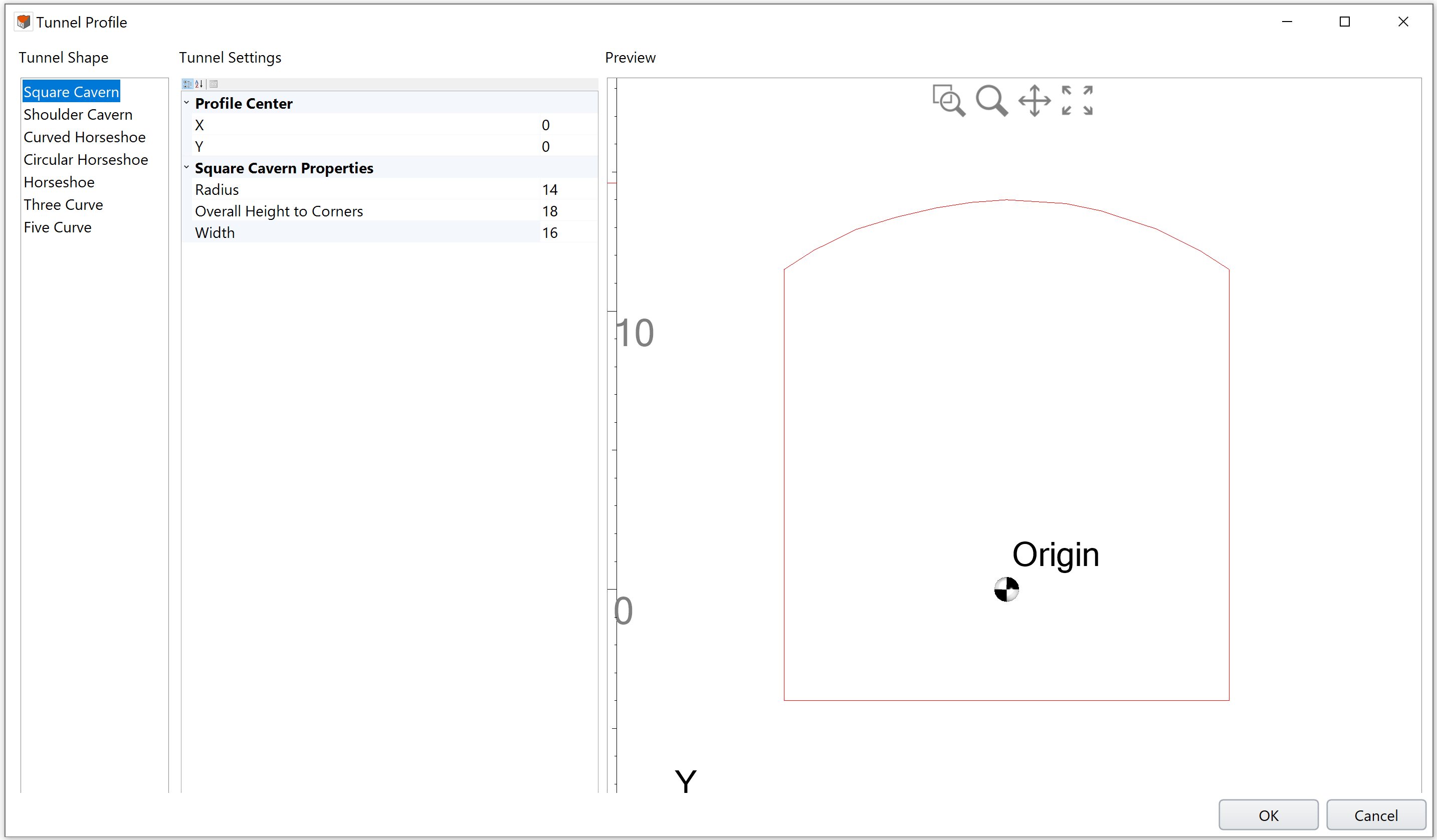
  3. In the Tunnel Shapes dialog. You may choose from the provided shapes:
    • Square Cavern
    • Shoulder Cavern
    • Curved Horseshoe
    • Circular Horseshoe
    • Horseshoe
    • Three Curve
    • Five Curve

  4. You can relocate the tunnel center of selected shape by adjusting x and y coordinates under Profile Center section. By default, the tunnel center is placed at the origin.
  5. Enter the tunnel properties to define the particular shape you have selected. The preview at the right of the dialog will be updated as you enter parameters.
  6. To include a Top Heading boundary within the tunnel, switch the Show Top Heading option to True and enter the top heading elevation and invert dish.
    • The Top Heading section is available for Curved Horseshoe, Circular Horseshoe, Horseshoe, Three Curve, and Five Curve shapes.
  7. When all tunnel parameters have been entered select [OK] in the dialog.
    1. For users who are using the Tunnel Shapes option inside the Tunnel Designer dialog -

      1. The tunnel profile will be added and shown in the viewport. See more information on the Tunnel Profile help page.
      2. Stop following proceeding instructions on this page. Continue your tunnel design to Tunnel Path, in the Tunnel Designer dialog.
    2. For users who are using the Tunnel Shape option directly from the Tunnels menu, please proceed on this page.
  8. You will then be prompted to enter the center point of the tunnel.
  9. In the dialog, define the tunnel shape center location in the model by entering global x, y and z coordinates. Use either method to define the Orientation:
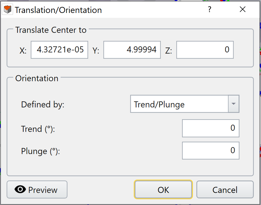
  10. Choose Defined by = Trend/Plunge – specify a trend angle and a plunge angle. See the help page Sign Convention - Trend/Plunge for trend/plunge sign convention in RS3.

    Choose Defined by = Vectors – specify a vector with XYZ components. The normalized vector will be shown below in blue text.

    Translation/Orientation dialog for Trend/Plunge method
    Translation/Orientation dialog for Trend/Plunge method
  11. After the center has been entered, click OK. The tunnel cross section outline will be added to the model.

Extrude Tunnel Face

After the tunnel cross section outline is created with Tunnel Shapes option, and it is added to the model, the next step is to extrude the tunnel face.

Use the Extrude option under Geometry menu to extrude the tunnel face. A 3D tunnel will then be made.

Rocscience logo, click here to return to the homepage Portal Account Portal Account Log In Log Out Home Shopping Cart icon Click here to search our site Click here to close Learning Tech Support Documentation Info Chevron Delete Back to Top View More" Previous Next PDF File Calendar Location Language Fees Video Click here to visit Rocscience's LinkedIn page Click here to visit Rocscience's YouTube page Click here to visit Rocscience's X page Click here to visit Rocscience's Facebook page Click here to visit Rocscience's Instagram page Click here to visit Rocscience's Reddit page Bookmark Network Scroll down for more Checkmark Download Print Back to top Single User Multiple Users RSLog RocFall3 CPillar Dips EX3 RocFall RocPlane RocSlope3 RocSupport RocTopple RS2 RS3 RSData RSPile Settle3 Slide2 Slide3 SWedge UnWedge RocTunnel RocSlope2 Commercial License Education License Trial License Shop safe & secure Money-back guarantee