Add Bolts
The Add Bolts option is used to add linear 1-dimensional bolt to a model in patterns. It is useful feature when user wants to apply various patterns of bolts to the model.
To add bolts as a bolt pattern to the model follow the steps:
- Select the Support workflow tab

- Select: Support > Bolts > Add Bolts or select the Add Bolts
 from the toolbar.
 - You will see the Add Bolts dialog. In this dialog, there are four tabs:
TIP: If you have selected the surface on which you want to apply the bolt to, then select Support > Bolts > Add Bolts to selected face. Refer to Add bolts to Surface for more information in RS3 Online Help.
- Shape
- Properties
- Surface
- Location
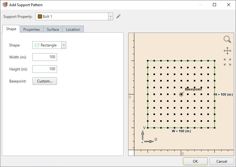
Shape Tab
Define Support Shape and Properties:
- Rectangle
- Width (m) and Height (m)
- Basepoint [default (U, V)= (0, 0) or custom; point of reference used to translate (U, V) coordinates to (X, Y, Z)]
- Circle
- Radius (m)
- Basepoint [default (U, V)= (0, 0) or custom; point of reference used to translate (U, V) coordinates to (X, Y, Z)]
- Polygon (use table to enter custom coordinates)
- Coordinates [U (m) and V (m)]
- Basepoint [default (U, V)= (0, 0) or custom; point of reference used to translate (U, V) coordinates to (X, Y, Z)]
Properties Tab
Define the properties of the bolts:
- Length (m): the length of the individual bolt in the bolt pattern
- Pattern Properties
- Horizontal Spacing (m): spacing of the bolts in horizontal direction with respect to the base point defined from shape property.
- Vertical Spacing (m): spacing of the bolts in vertical direction with respect to the base point defined from shape property.
- Pattern Angle: apply the rotation of the bolt patterns with respect to U and V coordinates in counter-clock wise direction.
- Pattern Offset (m) - pattern offset from basepoint (U,V) defined in Shape/Property Tab.
- Orientation
There are number of ways to define the orientation of the bolts: Vector, Normal, Trend/Plunge, Local (x,y,z).
- Vector: Assigns direction of the bolts to the model with vector defined by the user (the normal vector is normalized). The vector follow the signs of the global (x,y,z) coordinate of the model. i.e. if the bolt is applied in (0,0,1) for x, y, z input, the bolts will be applied in positive direction in z coordinate.
- Trend/Plunge: specify a trend and plunge (see Sign Convention for more information)
- Normal: assigns bolts normal to the model geometry.
- Local (x,y,z): Assigns bolts to the local (x,y,z) coordinates of the model. Notice that these are local x, y, and z coordinates, and will apply the bolts towards the geometry of the model.
- Staging
If your model is staged, you can specify the installation and removal stage of bolts.
- Install at stage - by default the installation stage will be set to the stage that you are currently viewing (i.e. the currently selected stage tab). You can enter a different stage if necessary.
- Remove at stage - by default the removal stage will be set to never. You can enter the stage at which the Bolts are to be removed (uninstalled), if applicable.
Surface Tab
Define where the support will be placed on the model (which model entity will be affected by the support placement)
- Projected on Terrain
- Spacing Mode (Orthogonal to Drilling Direction or Along the Surface)
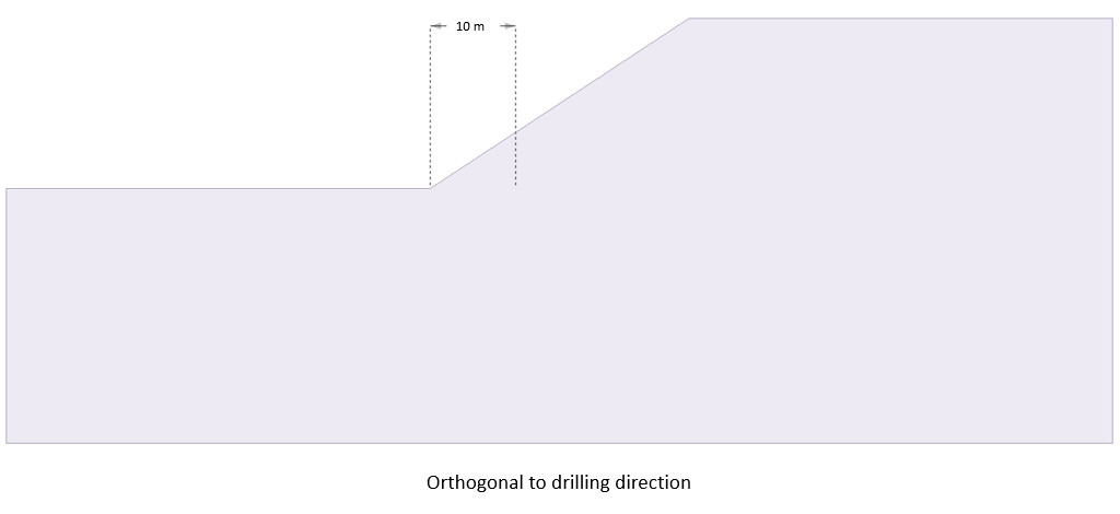
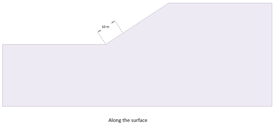
Spacing mode: Orthogonal to Drilling Direction vs. Along the surface
Orthogonal to drilling direction setting allows users to apply bolt pattern with spacing that is identified with projected surface plane. On the other hand, along the surface setting allows users to set spacing of the bolts along the distance of the geometry. Below shows difference in diagram:
On surface if the bolts are applied with constant value of 10 meters on slope, the difference between the two can be shown more clearly as shown below:
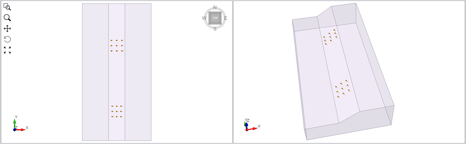
The one on the right side of the model in y direction is the bolt pattern applied with 10 m spacing with orthogonal to drilling direction whereas the one with left side of the model shows spacing option with along the surface. Notice that along the surface in this case has smaller spacing than the one with orthogonal direction due to different setting applied with each option as described above.
- Projected on Volume
- Volume
- Projection (available to project bolts in different planes: including top, bottom, left, right, back, or custom with different orientation)
- Spacing Mode (Orthogonal to Drilling Direction or Along the Surface)
Location Tab
Options here allow loads to be either placed freehand on the model using the Freehand Manipulation commands, or defined by X and Y coordinate on the modeling interface.
- Freehand Manipulation: these commands will minimize the large define load dialog and allow the user to place the load "Freehand" on the model
- Move Load: move the mouse around the modeling interface and click to place the load in the desired location
- Rotate Load: move the mouse to rotate the orientation of the load, using the center as the base
- Numerical Definition:
- Location: Enter X (m) and Y (m) coordinates to define where the basepoint (previously defined in the Shape tab) of the load will be located on the model
- Orientation: Enter an Angle to finalize the load definition