Form Closed Triangulation
The Form Closed Triangulation tool takes the selected surfaces and attempts to form one or multiple closed boundaries, depending on the shape of surfaces. This can be a time saving tool for independently processing large numbers of geometry.
- Select Geometry > Surface Triangulation Tools > Form Closed Triangulation

- If
more than one geometry is selected, a confirmation dialog will appear
that asks the user if they want to process all of the selected
geometries at once. The options are:
- Yes - Form closed triangulation of all selected geometries at once.
- No - Have each of the selected geometries processed independently.
- Yes - Form closed triangulation of all selected geometries at once.
Examples
Example 1:
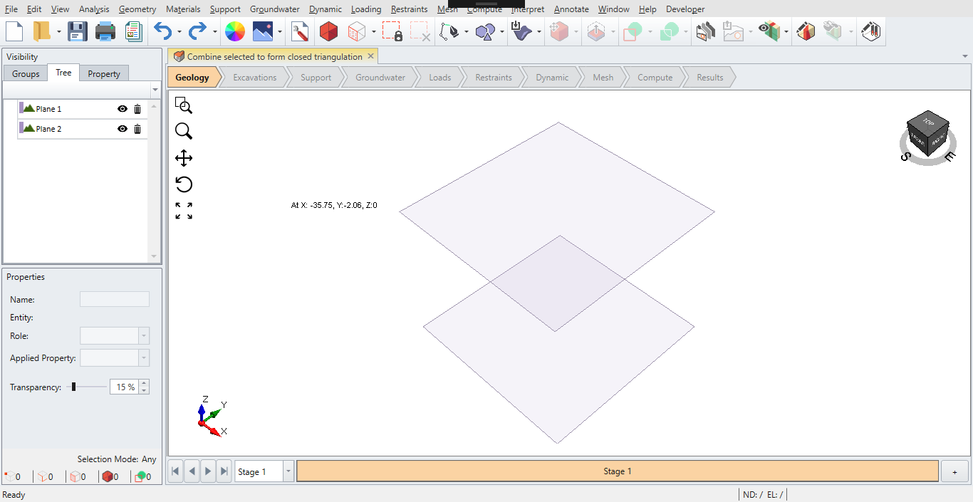
Open the attached project "Combine selected to form closed triangulation" and select both planes and run the command
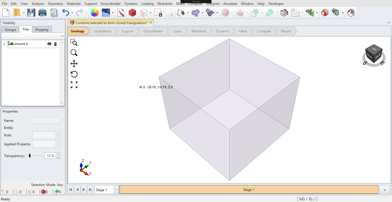
Yes: Creates a box from the two planes
No: Error is returned as each plane is processed independently. You would get the same result as if you select only one plane and run this command. It is not well defined how a convex hull can be created from a planar object as it has no volume.
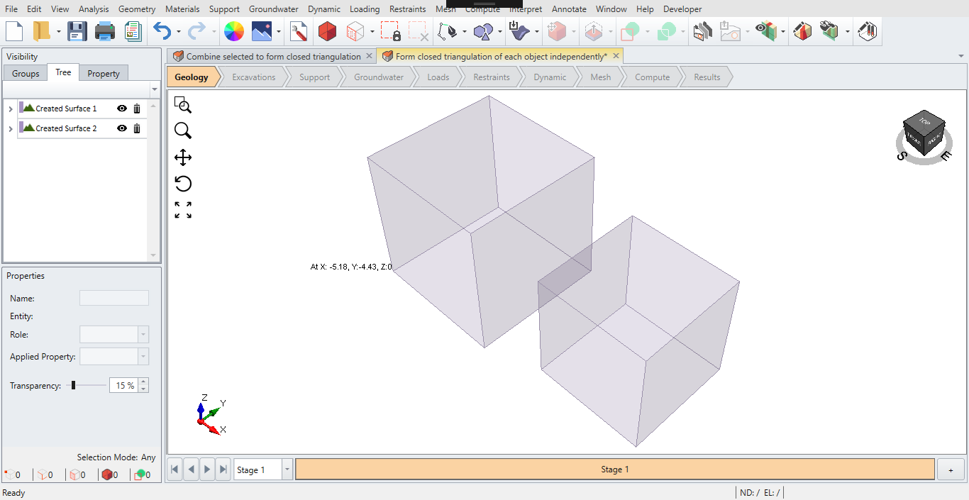
Example 2:
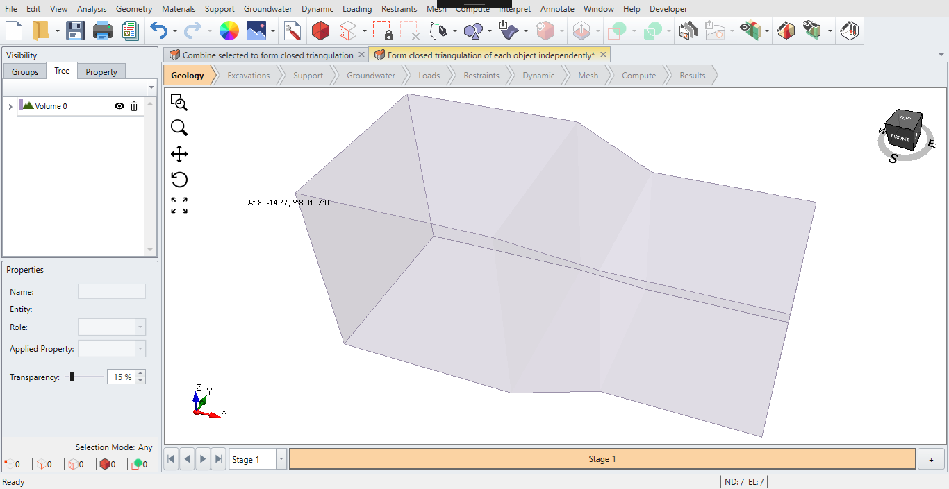
Open "Form closed triangulation of each object independently" and run this command with both boxes selected
Notice that the two boxes have a missing face. This is where the new option is useful.
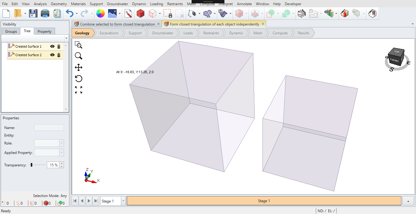
No: The two boxes are filled independently. Notice that Form Closed Triangulation is an alternative method to remove any hole on a supposed volume. If you have many of them, it would be a lot easier if you can run this on a batch of objects in one run.
Yes: This behaves the same as before. The two boxes are now created as one.