Deformed Configuration
After compute, the Deformed Configuration ![]() option from the Interpret menu becomes enabled. It is a result display option to visualize the deformation of the model. The deformed shape is generated based on the computed displacement data within finite elements.
option from the Interpret menu becomes enabled. It is a result display option to visualize the deformation of the model. The deformed shape is generated based on the computed displacement data within finite elements.
Note that:
- This option is applicable only for solid and liner entities, but not for embedded elements including piles, bolts, or beams.
- The Result Type from the Legend pane should be aligned with the entity type (e.g., set Result Type = Solids to display deformed solid entities; set Result Type = Liners for liners).
- By default, the contour on the deformed shape is based on the selected Data Contour from the Legend pane.
- The deformed shape can be customized with the deformation properties include the mesh, contour, scale, and other settings in the Properties pane.
- If the Reference Stages is active, the deformed configuration will also be updated accordingly.
- If there is any operation leading to another divide-all, the existing deformed configuration will be deleted.
To use the Deformed Configuration option:
- Compute the analysis and select the Results workflow tab.
- Select one or more entities from the Visibility Tree or with the Entity Selection
 from the toolbar (see Figure 2 below). Note that:
- Selected entities must be volumes in Geology/Excavation role or Liner elements.
- For Excavation role volumes, on their excavated stages, the boundaries touching the non-excavated volumes will still be shown.
- If no entity is selected, the external volume will be processed (see Figure 3 below).
- Select the Deformed Configuration
 from the Interpret menu.
 - The deformed shape will be displayed in the viewport. New entities named “Entity_Deformation” will be added to the Visibility Tree.
- Select a deformed entity under the Visibility Tree. You can customize the deformation shape with provided setting options from the Properties pane.
- By default, the setting is Deformed Contour with Global Scaling = Auto current stage and Scale Factor = 5. For more information about the scale settings and calculations, see the linked section below.
- By right clicking in the Visibility Tree and selecting the “Hide All But Selected Geometry” option, you can only show the selected entity in the viewport.
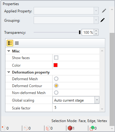
Figure 1. Properties pane
The two GIF below show the application of Deformed Configuration on a selected entity (Figure 2) and the external volume (Figure 3) respectively.
Deformation Properties
The deformation can be presented in one of the three ways:
- Deformed Mesh
- displays the deformed mesh of the entity
- Deformed Contour
- displays the deformed contour for the entity
- the displayed contour type is dependent on the chosen Data Contour from the Legend pane
- Non-deformed Mesh
- displays the original mesh of the entity
For the Deformed Mesh and Deformed Contour options, the deformation size can be adjusted with the scaling options, see the section below.
Show Faces
The Show faces option allows you to display the surfaces of the entity. It is applicable to be used with the Deformed Mesh or Non-deformed Mesh options.
Color
You can customize the color of the entity. It is applicable to be used with the Deformed Mesh or Non-deformed Mesh options.
Deformation Scaling
The deformation scaling can be customized with the combination of Global Scaling and Scale Factor options. They will take effect when Deformed Mesh or Deformed Contour option is activated, presenting the scaled deformed shape in the viewport. Note that:
- The Global Scaling and Scale Factor options are global, which means any changes in one entity will also be reflected to all other deformed entities in the model.
- The two options can alternatively be accessed by right clicking in the viewport, select Display Options
 , and click on the Advanced
page.
, and click on the Advanced
page.
Global Scaling
There are three types available:
- Auto current stage
- The scaling (α) is calculated based on data from the current stage and an user input Scale Factor value (i).
- Auto all stages
- The scaling (α) is calculated based on data from all stages and Scale Factor (i).
- To activate the option, all stages need to be clicked through to load all data.
- User defined
- The scaling (α) is solely governed by an user-defined Scale Factor (i).
The deformed shape is generated by updating the location of each node based on the displacement data in each direction:
Xi_new = Xi_orig + α * Ui_x
Yi_new = Yi_orig + α * Ui_y
Zi_new = Zi_orig + α * Ui_z
For Auto current stage and Auto all Stages options:
The scaling (α) taken to calculate the degree of exaggeration of deformation is as follows:
α = (0.01*i * max_dim) / max_disp
i is the user input value of the Scale Factor, which is set to 5 by default. It represents a percentage of displacement exaggeration. When Scale Factor = 5, the scale is 5% of the real dimensions; when Scale Factor = i , the scaled is i % of the real dimensions.
(max_dim) is the largest distance between the external volume and (max_disp) is the maximum displacement of the current or all stages. When the (max_disp) equals to 0, α is set to 0.
For the User defined option:
The scaling is solely controlled by the inputted Scale Factor (i). The deformation will be scaled by a factor of i (i.e., α=i).