Yielded Elements
An element yields when it transitions from a purely elastic behaviour to plastic (with permanent deformation occurring). The Yielded Elements options are used to display yielding in any element of the model, including solid elements (soil or rock volumes), support elements (bolts, beams, piles or liners), and interface/joint elements.
Display of Yielded Elements
After computing results, the user can display yielded elements as follows:
- Go to the Results workflow tab.
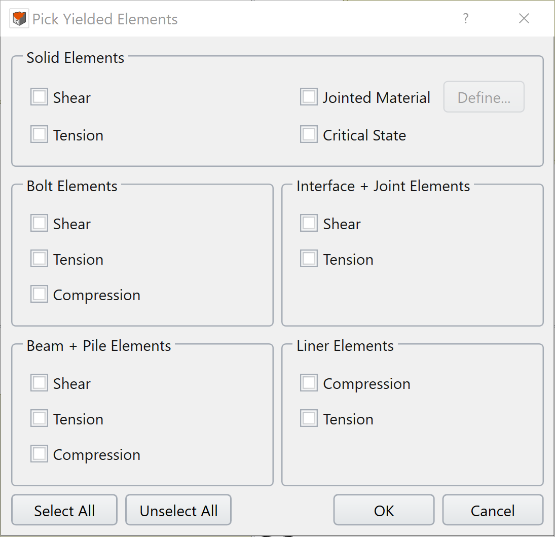
- Select: Interpret > Yielded Elements > Pick Yielded Elements.
- The Pick Yielded Elements dialog will appear, which shows all yielded element types.
-
Select the yielded element types to be displayed:
-
You can quickly select all
 or unselect all
 yielded types at once.
If "select all" is picked, it will automatically select all joints assigned to anisotropic materials
yielded types at once.
If "select all" is picked, it will automatically select all joints assigned to anisotropic materials -
The Define option for
jointed material allows the user to select
specific joint sets to display. Selecting the Define option opens the Pick Failure Type dialog which allows you to select whether to display shear and/or tension failure for any joint set defined in the
jointed material. In the example below, you can see that this model has 11 joint sets defined.
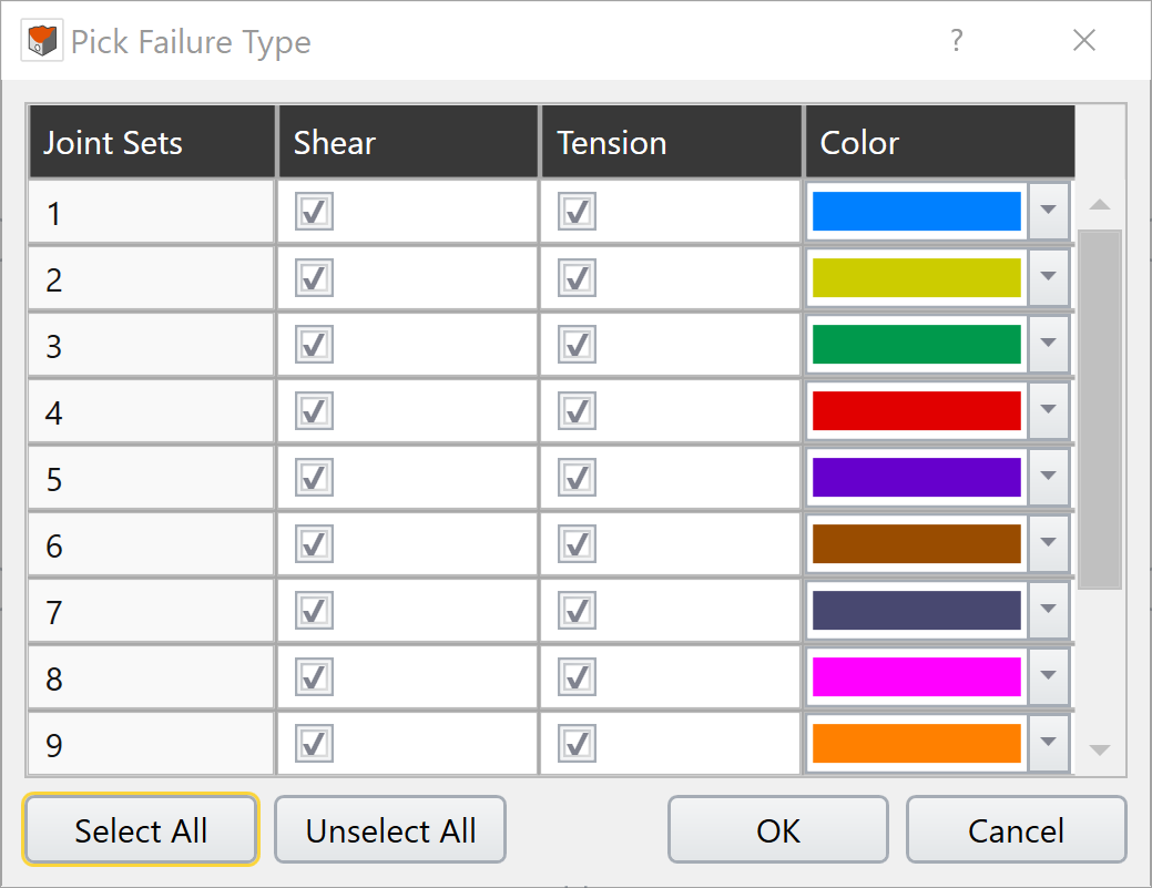
-
Joint set ID numbers are defined differently depending on the Failure Criterion chosen:
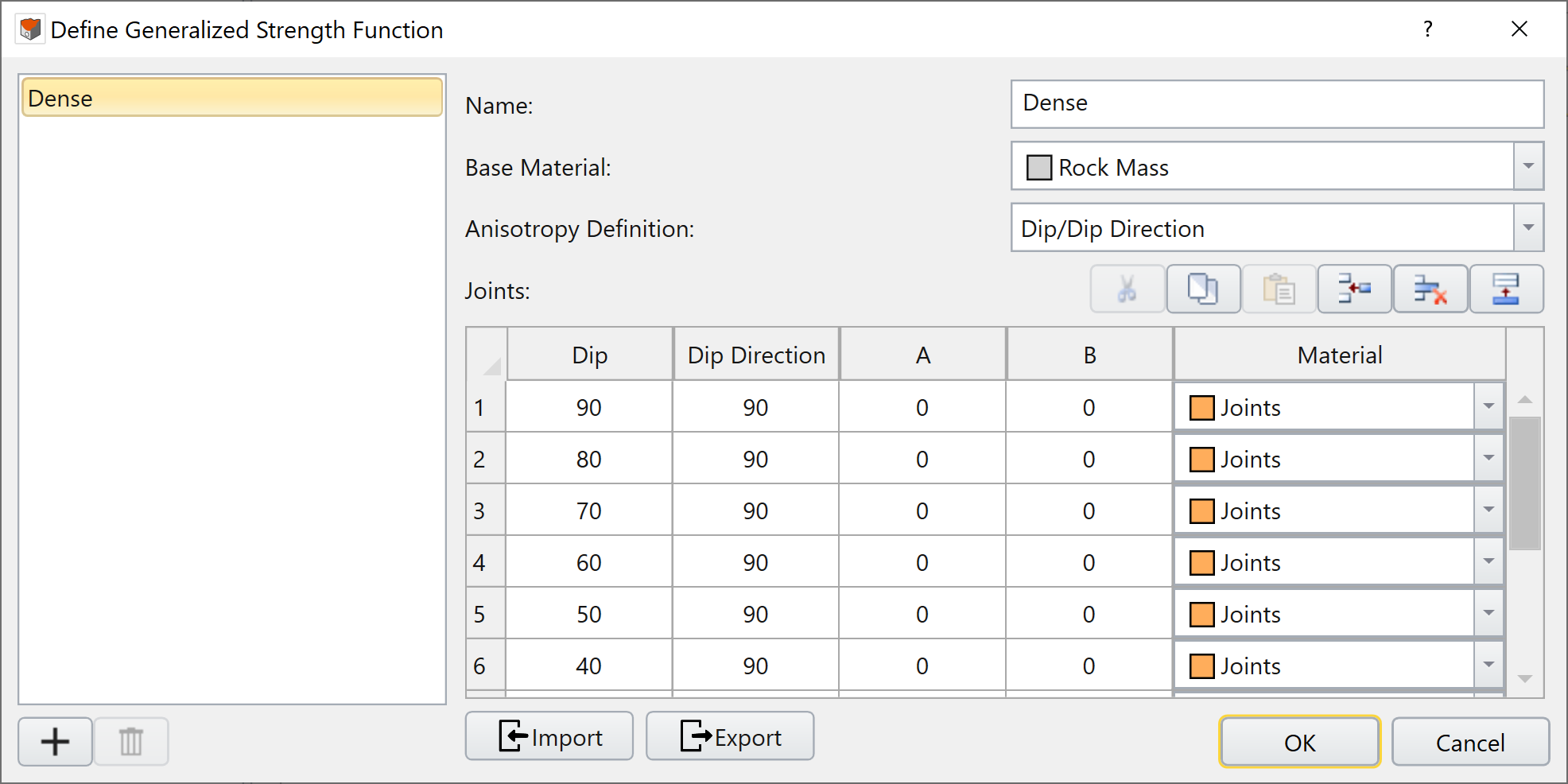
- Generalized Anisotropic: Joint Set ID number corresponds to the row of that particular joint defined in the Define Generalized Strength Function dialog.
- Jointed Mohr-Coulomb/Jointed Generalized Hoek-Brown: Joint Set ID number corresponds to the Joint Tab number
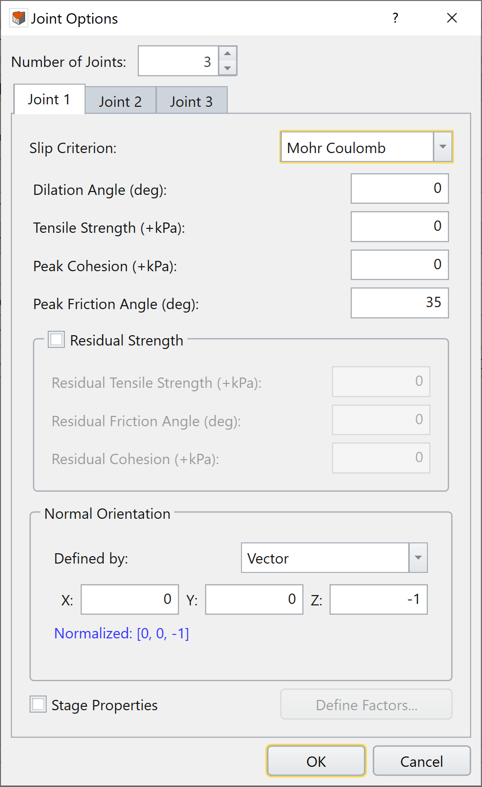
- Snowden Mod.Anisotropic Linear/Anisotropic Linear: Only Joint Set ID number of 1 is used and corresponds to yielding of the bedding plane.
-
The joint sets selected in the Pick Failure Type dialog will display all joint sets with that ID number for all active anisotropic material. The joint sets shown in the Pick Failure Type dialog is the maximum number of joint
sets in all active materials.
- Press OK to display the selected yielded element types and close the dialog. Depending on the element, yielding can be shown as symbols or as color shading on the element. The yielded element type and its corresponding symbol and/or color is shown at the bottom of the Legend in the Failures pane. See section below on Yielded Element Symbols and Colors for more details on the yielded element types.
- A Yielded Solid Elements entity will appear in the Visibility Pane if any yielded solid element types were chosen
-
You can quickly select all
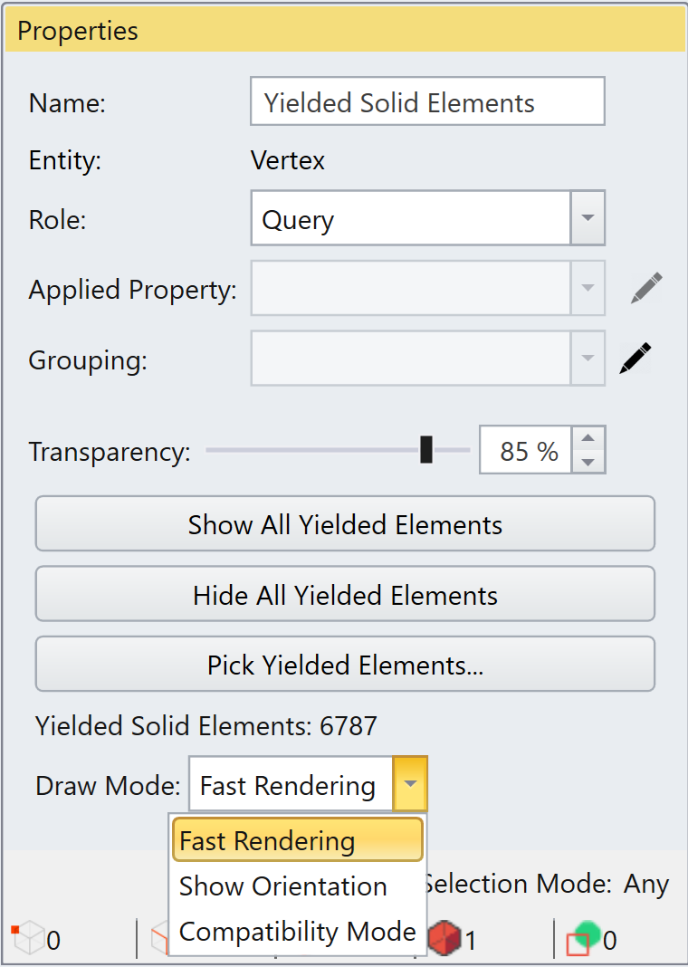
Selecting the Yielded Solid Elements entity in the Visibility Pane shows the following options in the Properties Pane:
- Transparency: does not affect the display of yielded elements.
- Show All Yielded Elements: display all yielded elements and is equivalent to Select: Interpret > Yielded Elements > Show All Yielded Elements.
- Hide All Yielded Elements: hide all yielded elements and is equivalent to Select: Interpret > Yielded Elements > Hide All Yielded Elements.
- Pick Yielded Elements: select yielded element types to show and is equivalent to Select: Interpret > Yielded Elements > Pick Yielded Elements.
- Draw Mode: Optimizes the drawing of yielded solid elements and has no effect on other element types (i.e. bolts, beams, piles, liners or interfaces/joints). Users can select:
- Fast Rendering: Ensure that Enable Hardware Acceleration is activated. Uses the fastest approach to construct and render solid yielded elements. To improve speed, this mode renders joint shear failure as spheres and tensile failure as vertical lines where their orientation does not relate to the joint orientation.
- Show Orientation: Ensure that Enable Hardware Acceleration is activated. This mode renders joint shear failure as disks where the orientation shows the joint orientation. The normal vector of the disk is equal to the normal vector of the joint plane. The joint tensile failure is rendered as a line where its direction is equal to direction of tension in the joint, the normal vector of the joint plane. This mode has no effect on other solid yield types.
-
Compatibility Mode: On some computers, the graphics hardware is not recognized, or otherwise does not support the other drawing modes. If a user's graphics hardware does not support the other drawing
modes, then the Compatibility Mode is automatically selected, and the other two modes become unavailable. This mode will render joint shear failure as disks and tensile failure as lines with their orientation matching
the joint orientation in the same manner as the Show Orientation mode.
Yielded Element Symbols and Colors
Solids
Solid elements model volumes of material which can be soil, rock, concrete and so forth. Yielded elements are displayed as follows.
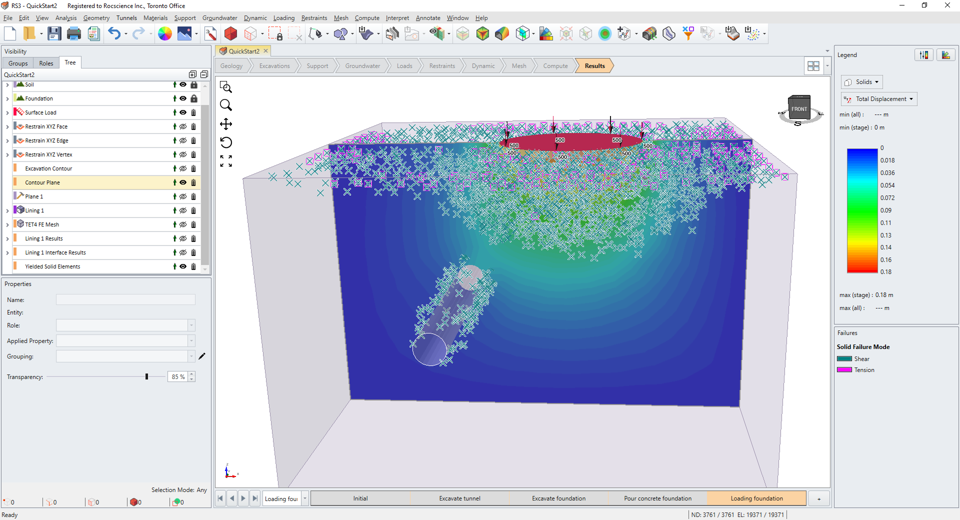
- Shear failure is indicated by a green "X" symbol.
- Tension failure is indicated by a pink square symbol.
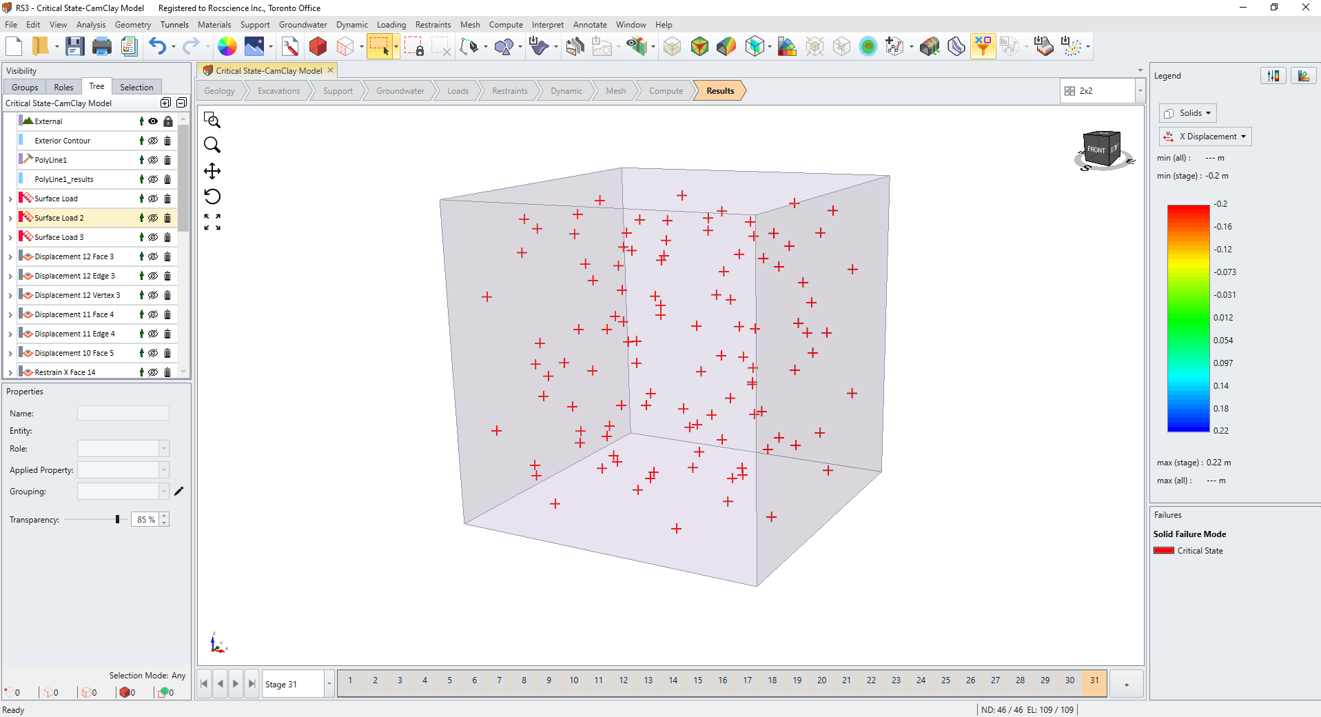
- If your model uses Cam-Clay or Modified Cam-Clay material strength models, then the Critical State Condition will be indicated by a red "+" sign.
-
When an Anisotropic material
is used, we can also show joint failure for each joint set. The symbol will depend on the Draw Mode selected:
- When the Draw Mode is set to Fast Rendering, joint shear failure is shown as a sphere.
- When the Draw Mode is set to Show Orientation or Compatibility Mode, joint shear failure is rendered as a disk, where the normal vector to the disk is equal to the normal vector of the joint plane (i.e. disk orientation matches joint orientation).
- When the Draw Mode is Fast Rendering, joint tensile failure is shown as a vertical line.
- When the Draw Mode is set to Show Orientation or Compatibility Mode, joint tensile failure is rendered as a line, where the direction matches the direction of tension for the joint (i.e. the normal vector of the joint plane).
The image below shows a model with solid elements yielded in shear and tension.
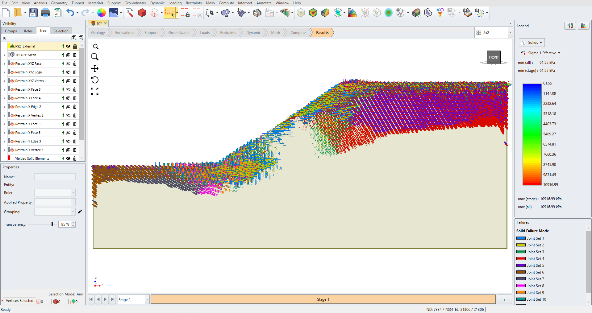
The image below shows a slope model with yielded joint sets within the solid elements that were defined using a jointed material.
The image below shows a triaxial test simulation of a Cam-Clay or Modified Cam-Clay material that has yielded based on the Critical State Condition.
Bolts
Yielded bolt elements are colored as follows.
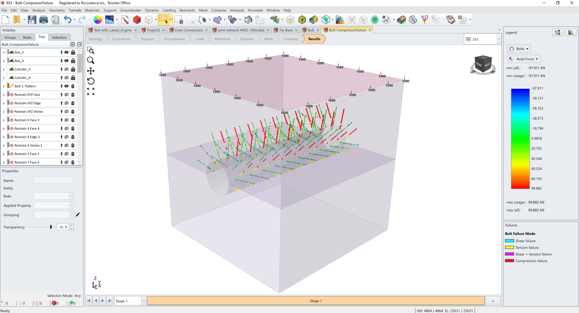
- Shear failure is colored in blue
- Tension failure is colored in yellow
- Shear and tension failure is colored in pink
- Compression failure is colored in red
The image below shows a supported tunnel model with yielded bolt elements in tension and compression.
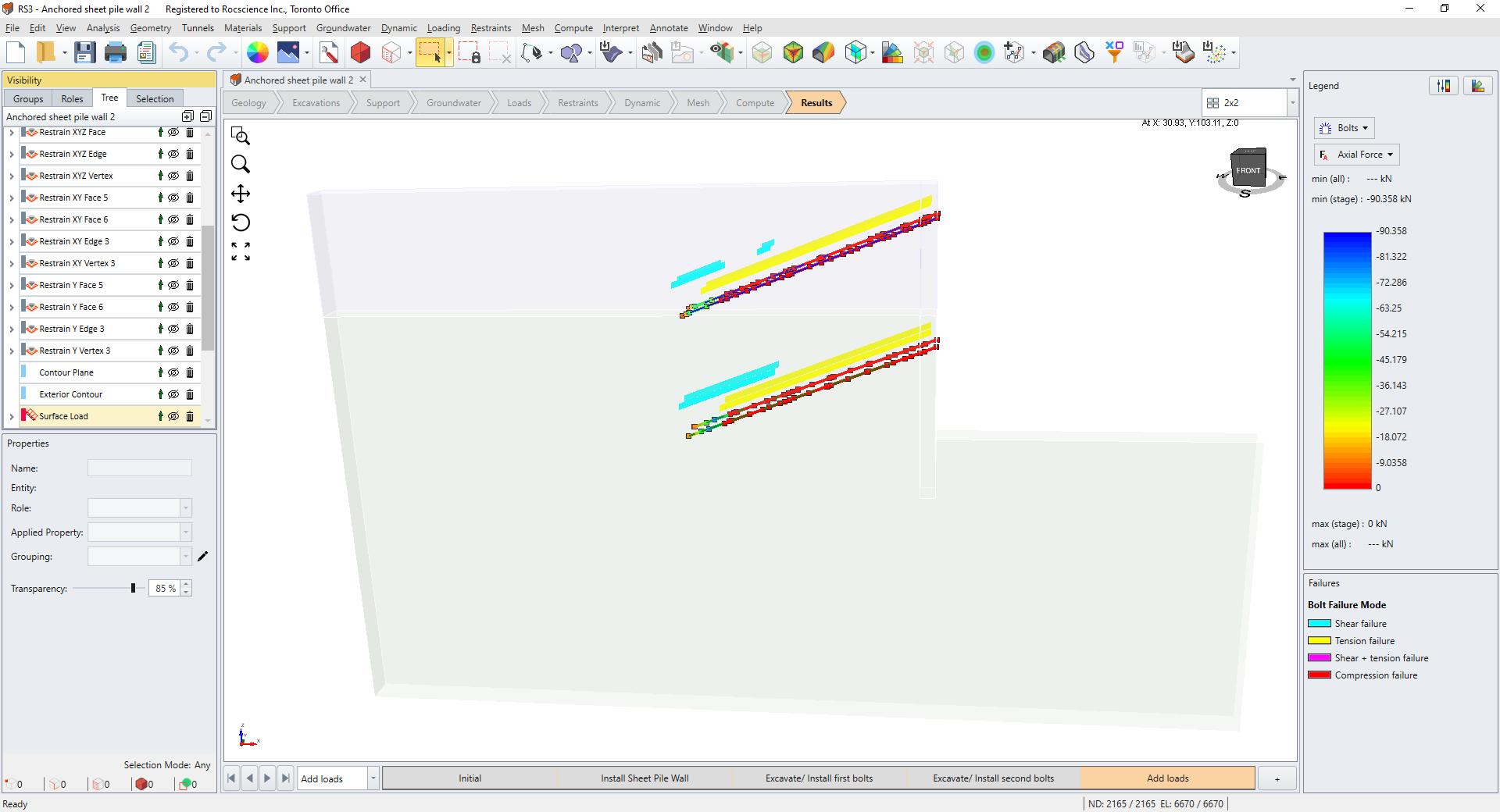
The image below shows an anchored sheet pile wall model with yielded bolt elements in shear and tension.
Beams & Piles
Yielded beam and pile elements are colored as follows:
- Shear failure is colored in blue
- Tension failure is colored in yellow
- Shear and tension failure is colored in pink
- Compression failure is colored in red
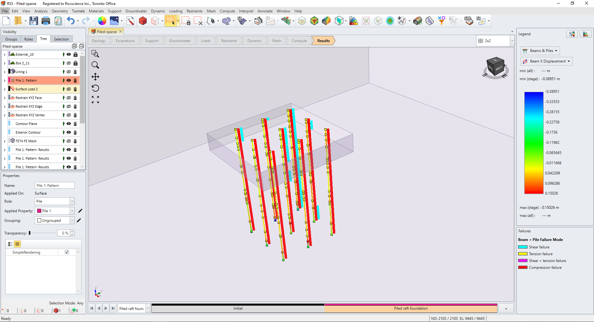
The image below shows a piled raft foundation model with yielded pile elements in shear, tension and compression.
Liners
Yielded liner elements are colored as follows.
-
Tension failure is colored in yellow
- Compression failure is colored in red
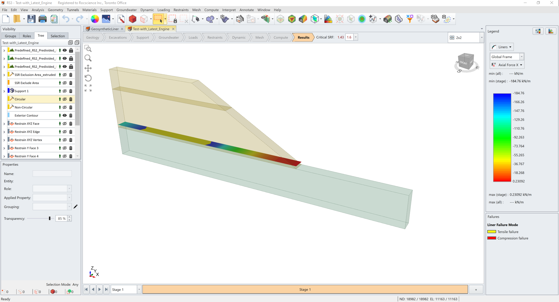
The image below shows a reinforced slope model with yielded liner elements in tension.
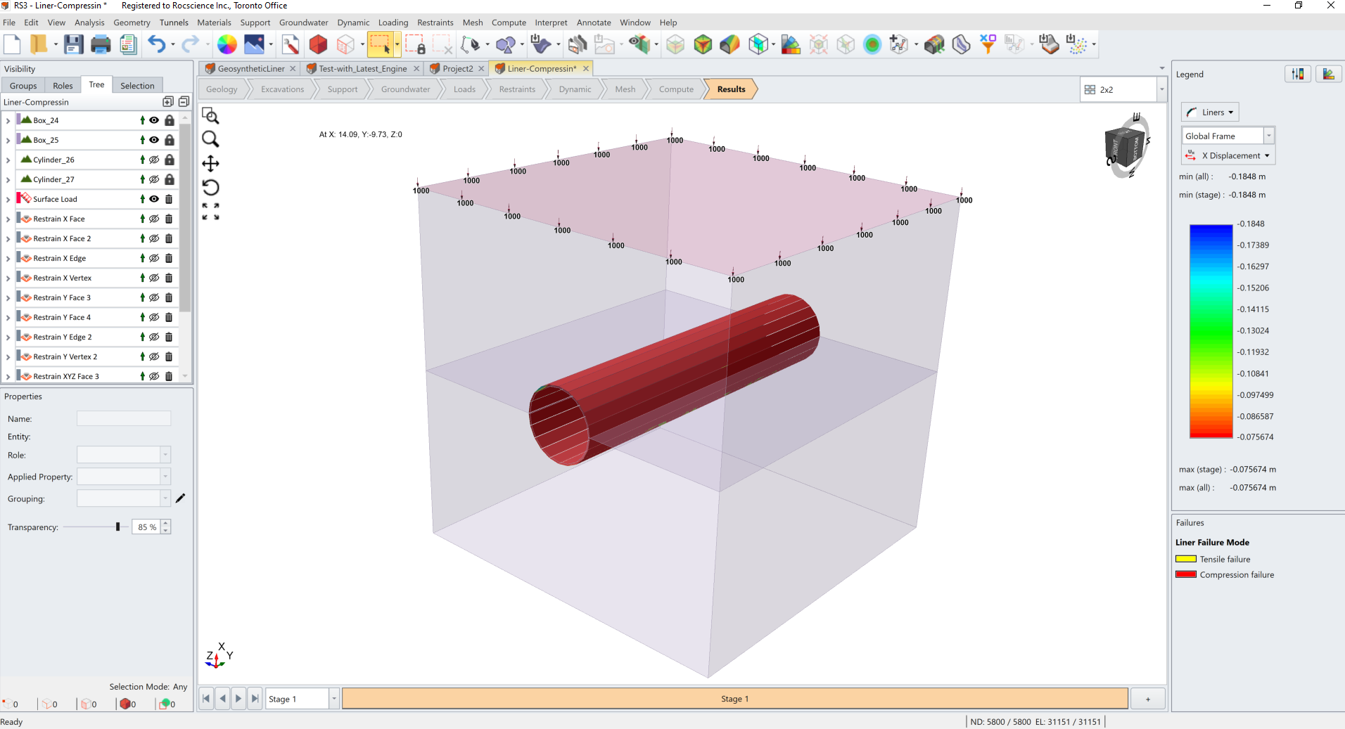
The image below shows a tunnel model with yielded liner elements in compression.
Interfaces & Joints
Yielded interface and joint elements are colored as follows.
- Shear failure is colored in blue
- Tension failure is colored in yellow
- Shear and tension failure is colored in pink
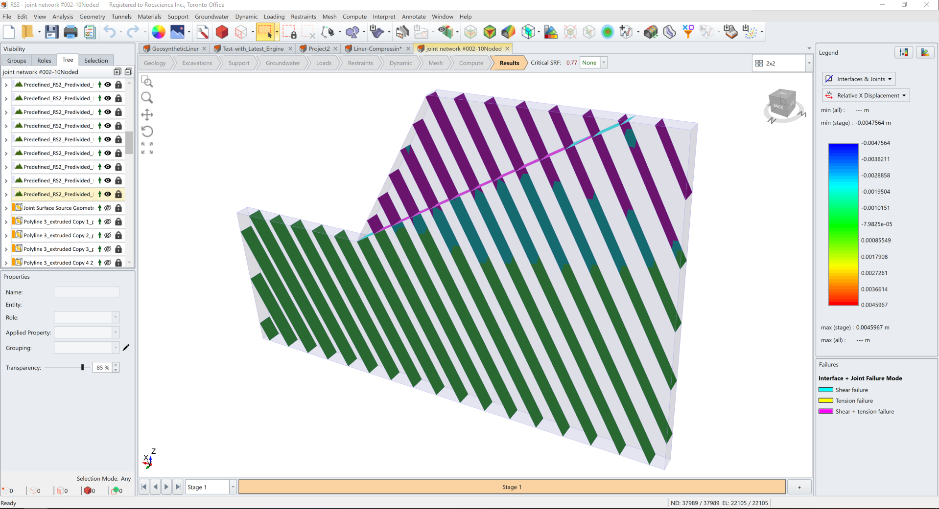
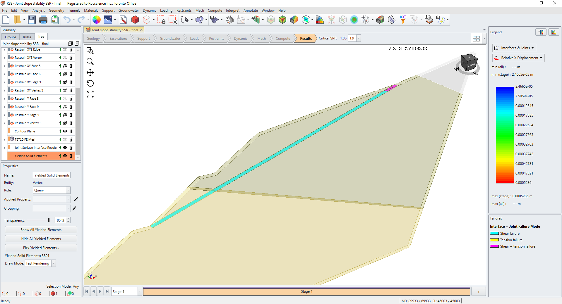
The image below shows a slope model where the defined joint surface has yielded joint elements in shear and tension.
The image below shows a slope model where multiple joint surfaces have yielded joint elements in shear and tension.