Sign Convention
XYZ Convention
The following convention is used for the XYZ axes of RS3 models:
- X-axis and Y-axis make up the horizontal plane
- Z-axis is always the vertical axis and is positive upwards.
- Rotation follows the right-hand rule where the thumb is pointing in the positive direction along the axis of rotation and the curled fingers indicate the positive rotation direction. This applies for all inputted angles in the program except for Trend and Plunge. See below for more information.
Trend and Plunge
The trend is the rotation angle about the vertical Z axis measured from the Y axis (north). Positive is taken as rotating from the Y axis (north) towards the X axis (east). Plunge is the rotation angle downwards from the horizontal XY plane after the Trend angle is applied.
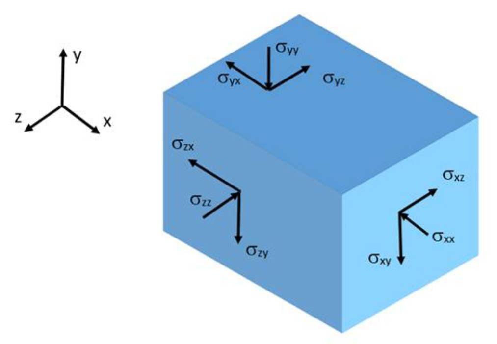
Stress Conventions
Stress convention for Solid Elements (Compression Positive)
Displacement, Force and Moment conventions for Liner Elements (Compression Positive)
Liner supports are modelled using plate elements, which are often not oriented along the global axis (Figure 1-a). The computed liner results in RS3 (displacement, force and moment) are provided in the global coordinate system. However, for design purposes, it is more useful to present the results in the liner local coordinate system. In Figure 1-b, a tunnel model is shown on the right image where the liner results would be most useful if presented in a liner coordinate system that follows the tunnel side faces.
(a) |
(b) |
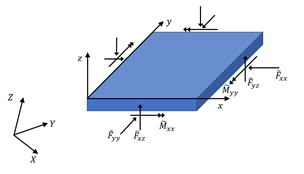
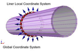
Figure 1. (a) shear and moment in liner local coordinates and (b) liner local coordinates in a tunnel model
RS3 provides option to visualize the results in any desired local coordinate system defined by the user. After the coordinate is defined, RS3 would transform all liner results into the new coordinate system.
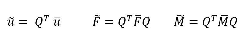
Considering a constant thickness of liner and noting the force and moment are presented per unit length, we can form the following matrices for displacements, forces and moments in the global coordinate system:
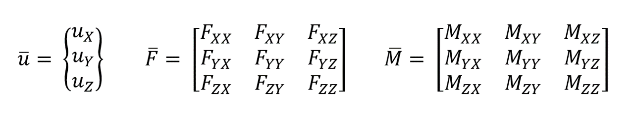
Here, the X, Y, and Z represents the axis in the global coordinate system. To transform the above relations into the local coordinate system with the axis of x, y and z, we need to form the transformation matrix Q. the components of this matrix can be found by
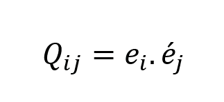
in which, ei is the unit vector in ith direction in the global coordinate system and e’j is the jth direction in the local coordinate system. Figure 2 illustrates the unit vectors in each coordinate system.
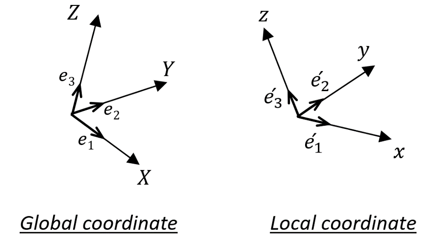
Figure 2. Unit vectors in global and local coordinate
By forming Q, we can calculate displacements, forces and moments in the desired coordinate system as: