The Default Water Condition, also know as Initial Water Condition (for Steady State or Transient analysis), allows users to define the ground water distribution through following methods
assigning a constant Pore Water Pressure or Ru value for a specific material,
assigning a PWP Point Set (point cloud distribution of PWP)
Default Water Condition switches to Initial Water Condition when the Groundwater Method is set to one of the Finite Element Seepage Analysis methods. Its role remains the consistent for the Finite Element Seepage Analysis methods to compute the pore pressure field; however, the defined parameter is only effective for the earlier stages before the Groundwater Boundary Conditions are applied. If both groundwater boundary conditions and initial water condition are applied, the groundwater boundary condition will take priority over initial water conditions.
To apply and initial water condition in the Define Hydraulic Properties dialog:
Select Define Hydraulic Properties from the toolbar or the Groundwater menu. This will open the Material Properties dialog to the Hydraulics tab.
Select the Initial Water Condition checkbox.
If you have added any Phreatic Surfaces in the model you can assign them to the material using the dropdown menu as the Initial Water Condition. You can also select Add Hydraulic Parameter
to use one of the below methods for calculating pore pressure. If you assigned a previously added phreatic surface, skip step 6 and 7.
In the Add Hydraulic Parameter dialog, assign the Type and Value of the parameter as desired.
Select OK. The hydraulic parameter is added to the Initial Water Condition dropdown list for the currently selected material. You may also edit or delete the currently selected Initial Water Conditions by selecting the Edit Hydraulic Parameterbutton or the Delete Hydraulic Parameter button, respectively.
Select the water condition to use as your initial groundwater condition.
Add Hydraulic Parameter - PORE WATER PRESSURE
The Default Water Condition can be selected to be defined as a Pore Water Pressure (PWP). A constant PWP is applied to all the nodes for a geometry that has the assigned material.
Add Hydraulic Parameter - RU VALUE
The Default Water Condition can be selected to be defined as an Ru value.
An Ru value simply models the pore pressure as a fraction of the vertical earth pressure. The vertical earth pressure is estimated from the unit weight and height of each material directly above a given point. The Ru Value is normally between 0 and 1. If a soil type has regions of differing Ru values, then a different material will have to be defined for each different Ru value. Appropriate material boundaries will have to be added to the model, in order to define the different soil regions.
Hu Coefficient
The Hu coefficient is a parameter that only becomes available when a Water surface is selected for Default Water Condition or Initial Water Condition. It typically ranges between 0 and 1 which multiplies the vertical distance from a point in the soil or rock to the water table (represented as Water Surface in RS3) to determine the pressure head. The Hu coefficient is used to calculate pore pressure as follows:
𝑢 = 𝑦𝑤 ℎ 𝐻𝑢
where:
𝑢 = pore pressure
𝑦𝑤 = the Pore Fluid Unit Weight (found in the Project Settings dialog)
ℎ = the vertical distance from a point to a Water Surface
𝐻𝑢 = the Hu coefficient for the material
If the distance ℎ is negative, (i.e. a point is above the Water Surface) then the pore pressure is set to zero.
There are two ways of defining the Hu coefficient - Auto or Custom.
Custom Hu
With the Custom Hu option, the user can enter their own value for Hu. A constant value for Hu coefficient must be specified. For example:
Hu = 1 would indicate hydrostatic conditions. This can be used where the Water Surface is horizontal. Where the Water Surface is inclined, setting Hu = 1 results in (generally) a conservative (high) estimates of the true pore pressure. The custom Hu of 1 is a default setting in RS3 to consider the worst-case scenario.
Hu = 0 would indicate a dry soil. In this case, pore pressure is always calculated to be zero. Setting Hu = 0 can be used to turn "off" the pore pressure for a material, although this can also be achieved by setting Water Surface = None.
Intermediate values of Hu can be used to simulate head loss due to seepage. This would be applicable where the Water Surface is inclined. However, the Auto Hu option, described below, can be used to automatically account for the inclination of the Water Surface.
If you are using the Water Surfaces to represent Piezometric Surfaces, it is advisable to use the Custom Hu option, with Hu = 1. This is because a Piezometric Surface is usually a direct representation of the pressure head.
Auto Hu
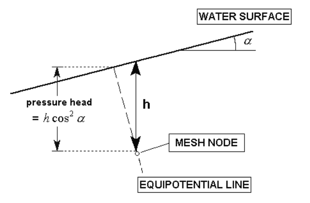
The Auto Hu option offers a simple method of estimating the pore pressure based on the inclination (angle) of the Water Surface. In the absence of more accurate data (e.g. Seepage Analysis results), this is a simple but useful method of approximating head loss due to seepage. With the Auto Hu option selected, RS3 automatically calculates a value of Hu, based on the inclination (angle) of the Water Surface, above a given point (mesh node). This assumes that the equipotential line (marked by dashed line on the figure below), which passes through the point, forms a straight line between the point and the Water Surface. This is strictly applicable for an infinite slope case.
A simple 2-dimension illustration below explains the pressure head calculation of a mesh node using the Auto Hu approach. Provided that α = the inclination of the Water Surface (above a given point) and h = vertical distance from the point to the Water Surface, pressure head equals to h cos2αℎ. For the 3D calculation in RS3, the inclination is the 3-dimensional minimum dip angle of the water surface above the node. This implies that the automatically calculated Hu coefficient is therefore equal to cos2α. For a horizontal Water Surface, α=0, and Hu=cos2α=1.
Automatic Calculation of Hu Coefficient
Stage Default Water Condition
If your model consists of multiple stages, and you require different default water conditions to be applied at different stages, for a given material, then within the Staging tab of the Material Properties dialog, use the Stage Hydraulic Properties option. This allows you to simulate, for example, the draw down of a water table at different stages.
To assign the staging of Default Water Condition:
With the Default Water Condition entered in the Hydraulics tab of the Material Properties dialog, navigate to the Staging tab and select the Stage Hydraulic Properties checkbox.
Now select the Add Stage button, until the number of rows is equal to the number of stages at which you need to specify a Default Water Condition. For example:
if you need to assign 3 Ru values at 3 different stages, then select Add Stage three times, so that a total of 3 rows appears in the data entry area below the Stage Hydraulic Properties checkbox.
If the Add Stage button is disabled, this means that you have not set the Number of Stages in Project Settings. In this case, go to the Project Settings dialog, and define the number of stages.
In each row, enter the Stage number at which the Default Water Conditions are to be assigned.
In each row, select the Default Water Condition representing that you wish to assign at the specified stage.
It is important to note that you only need to define the Stage and Default Water Condition information for the stages at which the Default Water Condition will change. You do not need to define this information at stages where the Default Water Condition does not change.
If you accidentally add too many rows with the Add Stage button, click the mouse on the row number and select the Delete Stage button, to delete the row.
When you are finished entering the Stage and Default Water Conditions, select OK to close the dialog.
When the analysis is run, RS3 will use the Stage and Default Water Condition information in the Material Properties dialog, to determine the correct Default Water Condition to be used at each stage of the analysis, for each material.

 dialog.
 from the toolbar or the Groundwater menu. This will open the Material Properties dialog to the Hydraulics tab.
 to use one of the below methods for calculating pore pressure. If you assigned a previously added phreatic surface, skip step 6 and 7.
 button, respectively.