Exclude Plastic Regions
If an RS3 model incorporates a nonlinear material, a plastic analysis to the whole model will be conducted to ensure that the stress state remains within the specified yield surface of the material.
The Exclude Plastic Regions  option enables you to exclude specific regions in the model from undergoing plasticity analysis by switching the material type to elastic. This option is useful to exclude regions with singularities that may cause non-convergence in plastic analyses.
In finite element analysis, there are circumstances that could cause false non-convergence, such as incorrect modelling procedure, incorrect input parameters, insufficient boundary conditions, or bad geometry. To avoid the singularity caused by bad geometry, affected areas can be excluded with this option. The material of the areas will be switched to elastic behaviour, and reduces the non-linearity of the model. As a result, the possibility of getting non-convergence due to bad geometry would be reduced.
- The Exclude Plastic Regions option has the OPPOSITE functionality to the Add Plastic Regions
 option.
 - This option is only available to plastic materials. See the How does the Exclude Plastic Regions work? section below for details.
- Plastic region and exclude plastic region can be added in the same model, while they must intersect with each other. See the Different Regions section below for details.
- This feature is available for joint and liners that are inside the exclude plastic region.
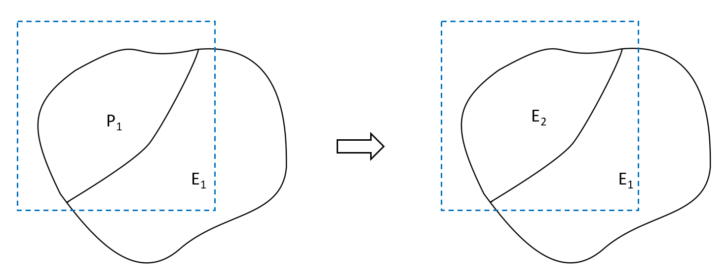
When an exclude plastic region is defined, the plastic material within the region will be switched to elastic. The material outside of the region will not be affected. Below shows a typical case of exclude plastic region application.
Example (case 1)
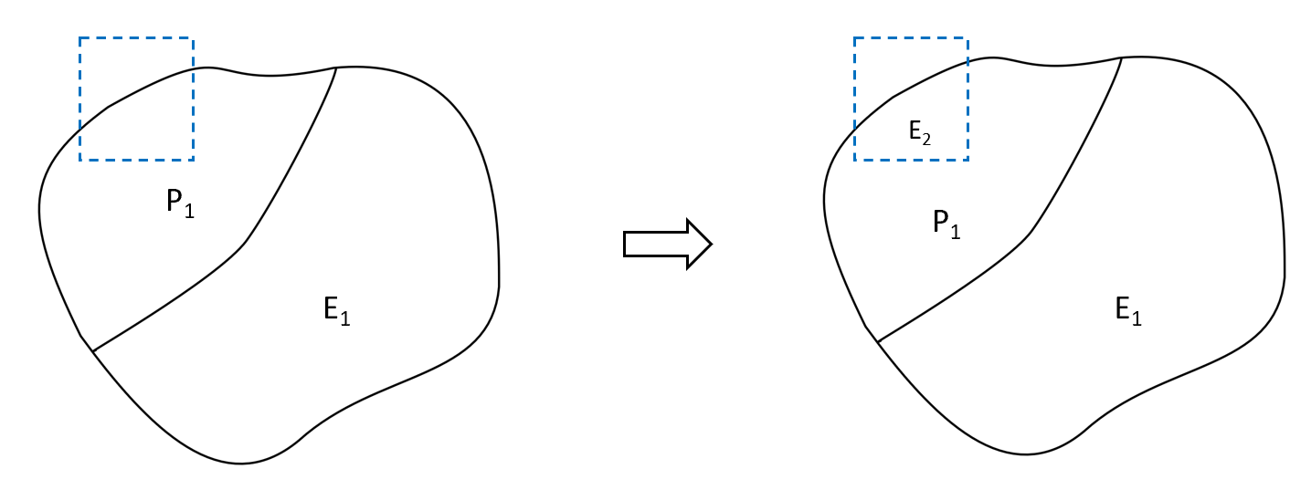
As seen in Figure 1, to start with, the model contains two material types, plastic (P1) and elastic (E1). An exclude plastic region (blue dashed box) is added to the top left corner of plastic part. As a result, the material within the region would be changed to elastic (E2) and the outside remains unchanged (P1 and E1).
Steps
Two methods are provided to define an exclude plastic region: a) by creating a box, and b) by setting a volume. Both methods are described below.
To use the Exclude Plastic Regions option:
- Ensure the material properties have been defined with the Define Material Properties option from the toolbar or the Materials menu. Ensure Material Type = Plastic under the Strength tab.
- Create a Box
- Select the Exclude Plastic Regions option from the Materials menu. You will be prompted to a dialog.
- The exclude plastic region be defined using either: the Create Plastic Exclude Region dialog, or the Freehand Manipulation tool
 .
.
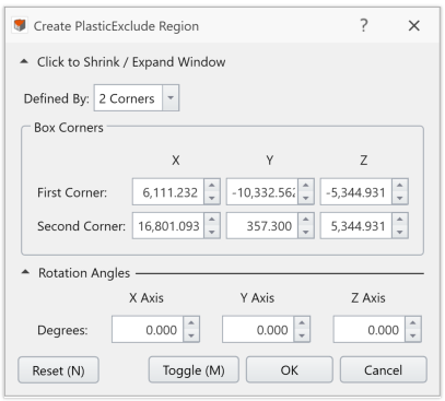
- From the Create Plastic Exclude Region dialog, choose a box dimension method from the dropdown list.
- If Defined By = 2 Corners, the XYZ coordinates for the two corner vertices of the box need to be specified.
- If Defined By = Dimensions, the XYZ coordinates for the center point of the box, as well as the length, width, and height dimensions of the box need to be specified.
The expandable Rotation Angles section can rotate the box. The rotation angles around the X, Y, and Z axes are required.
- A Freehand Manipulation tool will appear in the viewport. It is placed at the center of the box by default. You can hover the mouse to place the tool at any corner. When the Freehand Manipulator is at the center, you can drag the tool to translate the box, or drag the curve to rotate the box. When the tool is at a corner, you can drag the arrow to resize the box dimension along the corresponded axis.
- The dimension and rotation angle will be updated in the Create Plastic Exclude Region dialog.
Under the Create Plastic Exclude Region dialog, the Reset (N) button can reset the box. The Cancel button can exit the dialog.
- From the Create Plastic Exclude Region dialog, choose a box dimension method from the dropdown list.
When completed, select OK to apply and exit the dialog. The plastic exclude region will be added to the model and under the Visibility Tree as an entity named "Plastic Exclude Region".
To edit the region, you can use the Edit button from the Properties pane. See the Edit Plastic/Plastic Exclude Regions for details.
- Now, the area within the defined region will be elastic, and the rest of the model will remain unchanged.
- Continue to step 5 below.
- Set a Volume
- Select a volume entity either from the Visibility Tree, or from the model with the Entity Selection tool
 from the toolbar.
 - Select the Exclude Plastic Regions option from the Materials menu.
- The selected volume is now set as a plastic exclude region. An entity named “Plastic Exclude Region” will be added under the Visibility Tree.
- Now, the area within the defined region will be elastic, while the rest of the model will remain unchanged.
- Now, the area within the defined region will be elastic, while the rest of the model will remain unchanged.
- Repeat step 2-4 to add more plastic exclude regions. For more examples about single, multiple, or different regions, see the section below.
- When Completed, proceed to finish your model, apply Mesh and Restraints, and Compute.
- After Compute, you can view the RS3 compute file to see the material type changes due to plastic exclude regions.
How does the Exclude Plastic Regions work?
As mentioned, the Exclude Plastic Regions option is only available for plastic materials. Its typical use is as shown in the example above (see Figure 1).
Below shows the scenarios when elastic materials are involved. Single and multiple plastic exclude regions, as well as different regions are presented.
Single Plastic Exclude Region
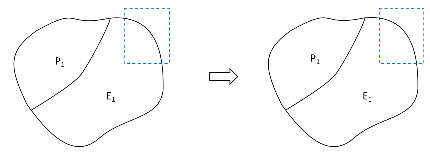
Case 2
Figure 2 below presents a case in which both elastic and plastic materials are included in the plastic exclude region, represented by a blue dashed box. In this case, the included plastic material will be changed to elastic (E2). The rest of the model stays unchanged.
Case 3
Figure 3 below shows when only elastic material is included in the plastic exclude region, represented by a blue dashed box. In this case, no change will occur either inside or outside the region.
When hitting Compute, a message will pop up: “The plastic exclude regions do not affect the model.”
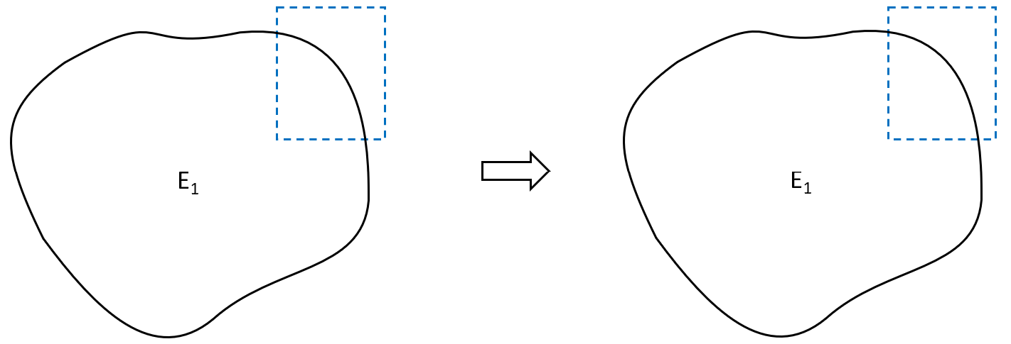
Case 4
As shown in Figure 4 below, an addition of a plastic exclude region within a model that solely consists of elastic material model does not make changes to the material behavior.
When hitting Compute, a message will pop up: “The exclude plastic regions do not affect the model.”
Multiple Plastic Exclude Regions
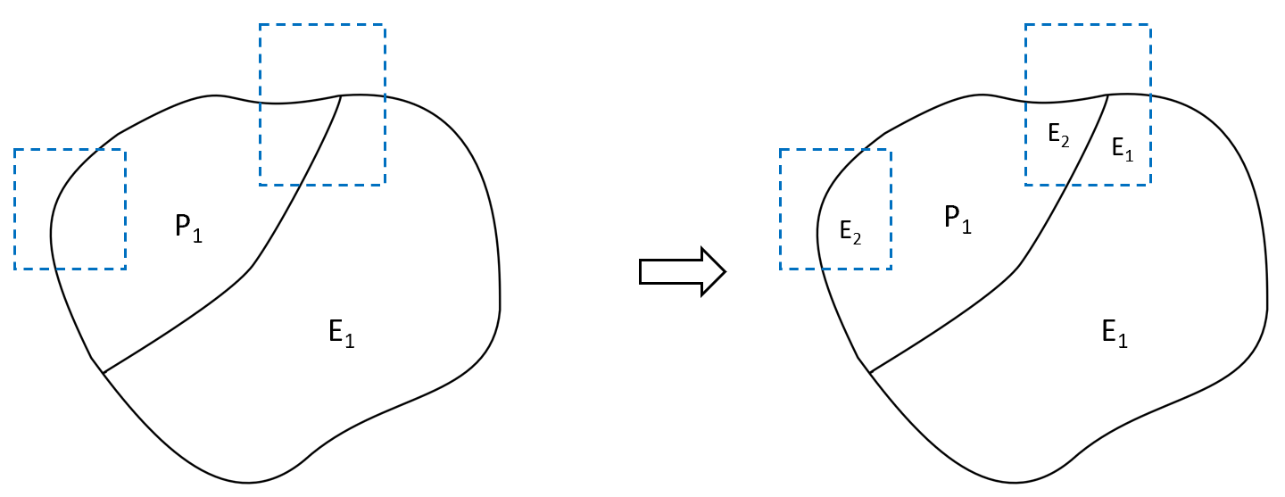
Case 5
Multiple exclude plastic regions are supported in RS3. As seen in Figure 5 below, two plastic exclude regions are added to the model. The plastic material inside the two regions is switched to elastic (E2). All other part of the model remains unchanged.
Different Regions
Add / Exclude plastic regions can be applied in the same model at the same time. Two cases are shown below.
- Each region must intersect with a region of the other type. Otherwise, it is not applicable (see Figure 6).
- The material type of intersected regions is governed by the final layer of the Add /Exclude plastic regions that is applied to it (see Figure 7).
Case 1
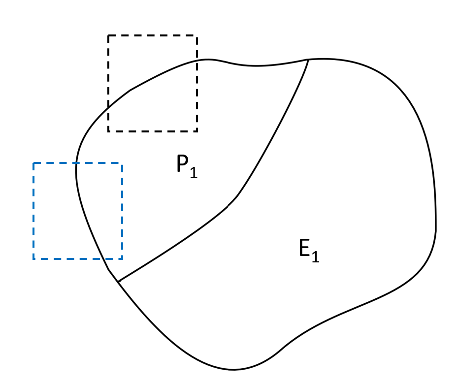
Figure 6 shows an invalid example, where two different regions do not intersect. The black dashed box represents a plastic region, and the blue dashed box represents an exclude plastic region. In such cases, a warning message will display: “New region needs to intersect a plastic region / exclude plastic region.”
Case 2
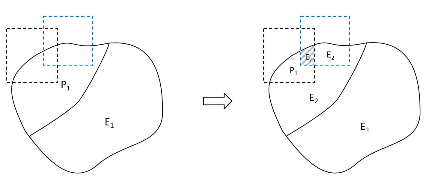
Figure 7 below shows a valid example. A plastic region is added FIRST (black dashed box), and an exclude plastic region (blue dashed box) is added AFTER. An intersected area is included.
The plastic material within plastic region remains plastic (P1), the plastic material outside this region is switched to elastic (E2). The plastic material within exclude plastic region is switched to elastic (E2). To be mentioned, the intersecting area (shaded) is switched to elastic (E2) – since the exclude plastic region is added the last.