Discrete Strength Function
The Discrete Strength Function option allows you to define Mohr-Coulomb shear strength parameters (cohesion, friction angle) at a grid of discrete points within a material. The shear strength at any point within the material is then interpolated from the data at the grid points. This allows you to define any type of strength distribution within a material.
- Shear strength may be specified for either the undrained case (cohesion only), or drained (cohesion and friction angle).
- The grid point locations can be user-defined, randomly generated or at the center of each finite element.
- Elastic modulus can also be defined at each grid point for a discrete strength function.
- Randomization can be applied to the values of strength or modulus by defining a statistical distribution for each parameter.
To define a Discrete Strength Function:
- Set the Failure Criterion = Discrete Function in the Define Material Properties dialog.
- Select the Edit button.
- You will see the Define Discrete Strength Function dialog.
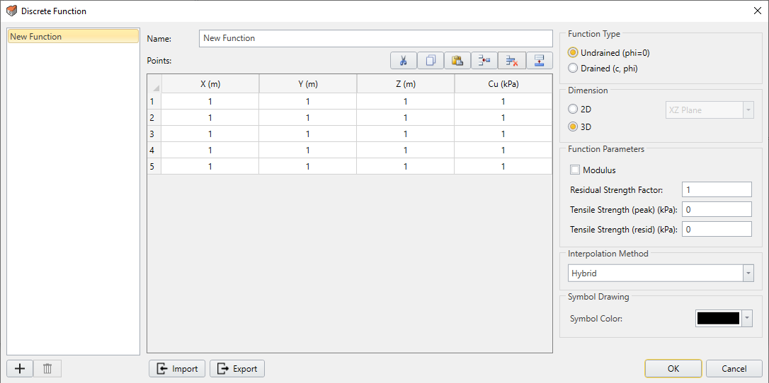
Discrete Function Dialog - Enter a Function Name in the list at the left of the dialog.
- Select the Function Type – Undrained (phi=0) or Drained (c, phi).
- Enter the Discrete Strength Function data in the data entry grid.
- If the Function Type = Undrained, you will be able to enter the undrained Cohesion (Cu) at X , Y coordinates.
- If the Function Type = Drained, you will be able to enter Cohesion and Phi at X , Y coordinates.You can use the buttons at the top of the data entry grid, to help carry out editing of the data (i.e. insert row, remove row, copy, paste etc)
- Select an Interpolation Method. This will determine the method used to interpolate the strength parameters at any point in the material. For details about the various Interpolation Methods, see the Interpolation Method topic in the Project Settings section of this Help system.
- You can select the type of Symbol and colours which will be used to display the location of the Discrete Strength function data points on the model.
- Several additional options are available in the discrete strength function dialog, including Modulus, Residual Strength Factor, Tensile Strength, and Randomization. See below for details about these options.
- When all data points have been entered, select OK, and you will be returned to the Define Material Properties dialog. The Name of the function you have just defined will appear in the Discrete function list. By selecting a Function Name from this list, you can apply a Discrete Function to any material in the properties dialog.
Modulus
When you define a discrete strength function, you can also choose to define a discrete distribution of elastic modulus for the same material. To do this:
- Select the Modulus checkbox in the Discrete Strength Function dialog.
- A column will appear in the dialog for entering values of elastic modulus at the grid points.
- You can also define a distribution of residual elastic modulus by selecting the Modulus (residual) checkbox. This checkbox is only available if you have enabled the residual elastic modulus option in the Define Material Properties dialog. The residual elastic modulus is used if material failure occurs.
Residual Strength Factor
The Residual Strength Factor is used to define the residual strength after failure for a discrete strength function. The cohesion and friction angle at each grid point is multiplied by the residual strength factor, in order to obtain a distribution of residual strength parameters for the discrete strength function. The residual strength distribution is used if material failure occurs. The default value of residual strength factor = 1, which implies perfectly plastic material behaviour (i.e. residual strength = peak strength).
Tensile Strength
Tensile strength can be specified for a discrete strength function by entering values of Tensile Strength (peak) and Tensile Strength (residual). The tensile strength values are constant for all grid points (i.e. you cannot define a distribution of tensile strength for a discrete strength function).
Randomize
You can apply statistical randomization to the discrete strength function values (cohesion, friction angle, modulus) by selecting the Randomize button in the Discrete Strength Function dialog.
- In the Discrete Strength Function dialog select the Randomize button.
- You will see the Randomize dialog which allows you to define a statistical distribution for each discrete function variable (cohesion, friction angle, modulus, residual modulus).
- For each variable you can choose from one of the following statistical distributions: Normal, Uniform, Triangular, Beta, Exponential, Lognormal, Gamma or None. Enter the standard deviation, relative minimum and relative maximum, as applicable for each distribution. If you want the variable to be constant, then set the Statistical Distribution = None.
- The minimum and maximum distribution values are specified as relative distances from the mean, rather than absolute values. For example, if the mean friction angle = 25 and the relative minimum and relative maximum = 5, then the actual minimum = 20 and actual minimum = 30. This simplifies the data input.
- For a normal distribution, over 99 percent of samples fall within 3 standard deviations of the mean value. You can use the following shortcut to determine the relative min and max values. Enter the standard deviation for a variable and select the
 button. This will automatically calculate appropriate relative min and max values for that variable and enter them in the spreadsheet. This is a handy shortcut when using a normal distribution.
 - You can choose one of the following Randomize Options to determine the location of the discrete function points:
- Use mesh - this will create a point at the centroid of each finite element in the material
- Use pre-existing points - if you have entered x,y locations in the Discrete Strength Function dialog, then these points will be used
- Generate random points - this will generate a user-defined number of points randomly within the material region
- Use density - this will generate a user-defined density of points randomly within the material region
- When you have finished defining the random variable distributions and chosen the Randomize Option, select OK in the Randomize dialog. This will generate statistical distributions for each variable and randomly apply the values to the points determined by the Randomize Option selected in the previous step.
- In the Discrete Strength Function dialog you will see the randomly generated values entered in the spreadsheet. Select OK to return to the Define Material Properties dialog.
- The discrete strength function values can be viewed in the RS2 Interpret program as described below.
Import / Export
Discrete Functions can be Exported (saved) in a separate functions file, and Imported into other RS2 files so that you do not have to re-define a Discrete Function if it is required for another RS2 file.
To Export (save) a Discrete Function:
- Select the Export button in the Define Discrete Strength Function dialog.
- In the Save As dialog, enter a filename, and save the file. Note: the default filename will use the Function Name, but this can be changed if required.
To Import a Discrete Function:
- Select the Import button in the Define Discrete Strength Function dialog.
- In the Open File dialog, open the Discrete Function file that you wish to import, and it will be imported into the Define Discrete Function dialog. NOTE: file formats which can be imported include:
- Comma, Tab or Space delimited text files
- .FN6 function files created with the Export option in RS2 or Slide.
- DXF files
- Select OK to add this function to the list of currently defined Discrete Strength Functions in the current model.
Display of Discrete Strength Function
When a Discrete Strength Function has been defined for a material, the function will be displayed on the model as indicated by a symbol at each x,y location defined in the function. The Symbol used for the function is the symbol selected in the Define Discrete Strength Function dialog. The strength function value(s) at each location can be displayed by selecting the checkbox in the Display Options dialog.
In the RS2 Interpret program, approximate contours of the interpolated Discrete Function can be displayed on the model by selecting the data name from the contour data drop-list in the toolbar (e.g. Cohesion Peak, Cohesion Residual, Friction Angle Peak, Friction Angle Residual). Discrete strength function data is treated as a user-defined variable in the RS2 Interpret program.
The interpolation results should always be looked at to ensure that the interpolation correctly simulates your field data. If it does not, then either more data points should be used or a different interpolation method. Since no interpolation method is guaranteed to work for all datasets, different methods should be tried in order to determine the best method for your data. If you have used the Randomize option, then you may need to check your statistical input parameters or the randomization method.
To define your material (e.g. rock or soil) properties:
- Select the Geology
 or Excavations
  workflow tab.
 - Select Define Materials
 from the toolbar or the Materials menu.
 - By default there are five (5) materials available to be edited. If additional materials are required, you can select the Add
 button to define the number of required material types. You can define up to 100 different material types in the Material Properties dialog. See the following topics for details.
- Initial Element Loading
- Unit Weight
- Strength Properties
- Stiffness Properties
- Staged Material Properties
- Datum Dependent Properties
- Unsaturated Shear Strength
- Jointed Material
- Hydraulic Properties