Cross-Section Tunnel Design
1.0 Introduction
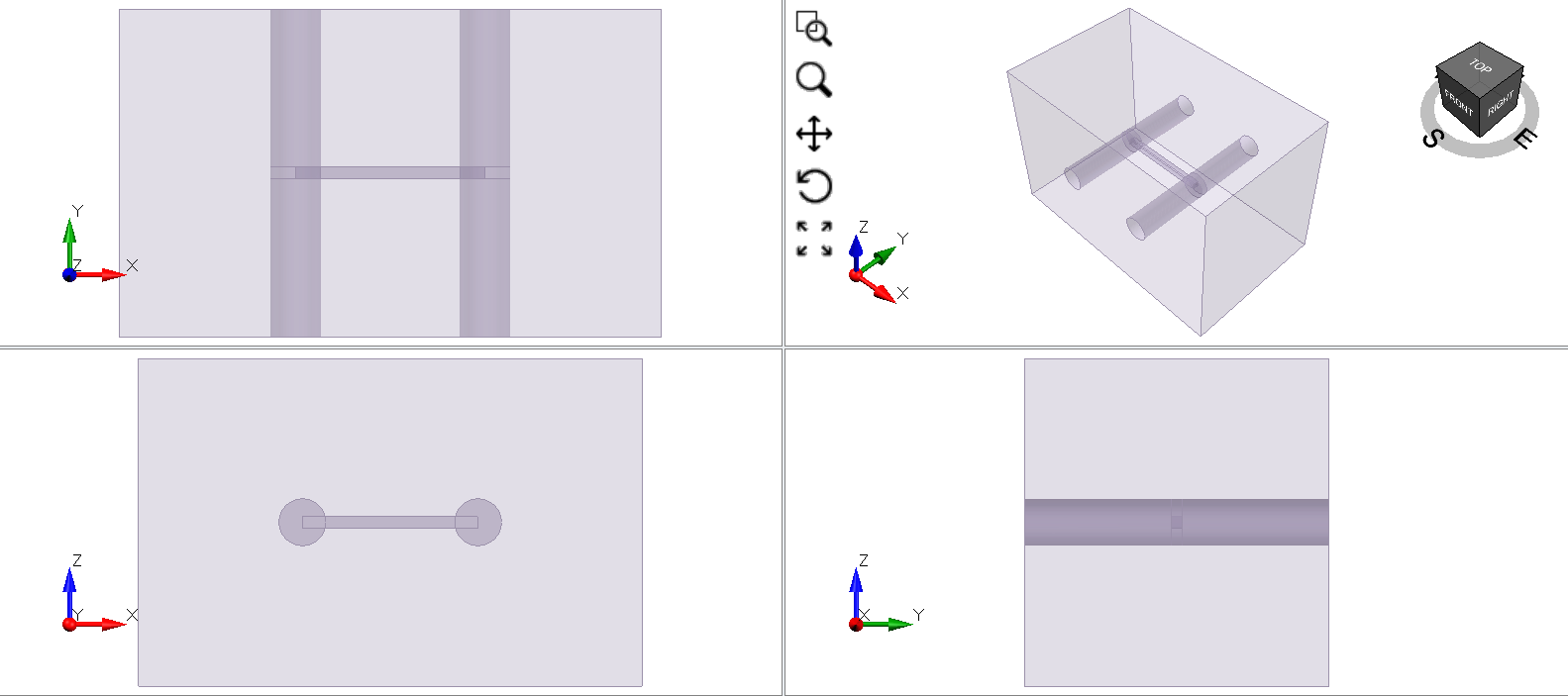
This tutorial demonstrates 3D cross tunnel design using the Tunnel Designer in RS3. You can use the Tunnel Designer to create tunnels with different shapes and apply them in various locations to create intersecting tunnels as shown below.
We will create the model from a new file. The final model can be found in Tunnel Designer - cross-section.rs3v3 file from Files > Recent > Tutorials folder in the RS3 menu.
2.0 Tunnel Design
2.1 GEOMETRY
Let’s start by creating an external box:
- Select: Geometry > Create external box.
- Enter the following values:
- Box Center: 15, 31, 0
- Dimensions: 86 ,62, 56
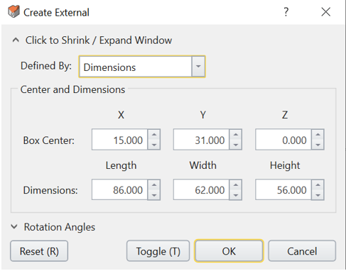
- Click OK.
2.2 TUNNEL DESIGNER
We will now create a tunnel using Tunnel Designer.
- Select: Tunnels > Tunnel Designer.
- First, we will create a circular tunnel. Select Draw > Circle on the right side of the polyline pane.
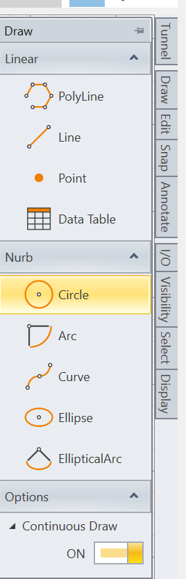
- Enter the coordinates 0,0 for center and press ENTER.
- For radius, enter 4 and press ENTER.
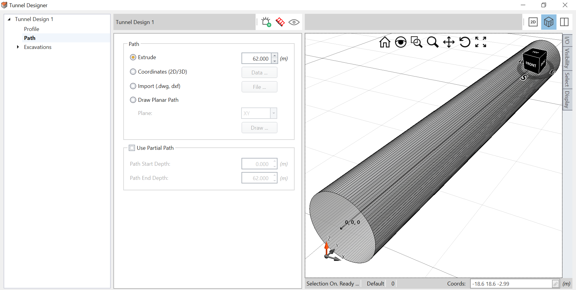
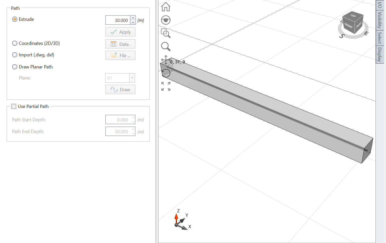
- Now select Path under Tunnel Design 1.
- Select Extrude, enter 62 m and press ENTER.
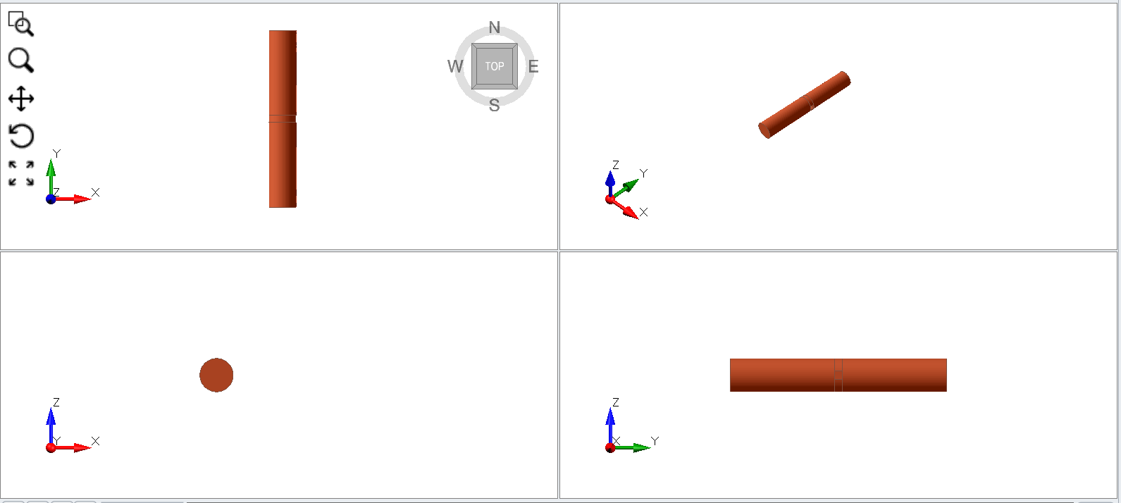
You will see the extruded tunnel as shown below.
- Now check the box Use Partial Path and enter Path Start Depth = 0 and Path End Depth = 30.
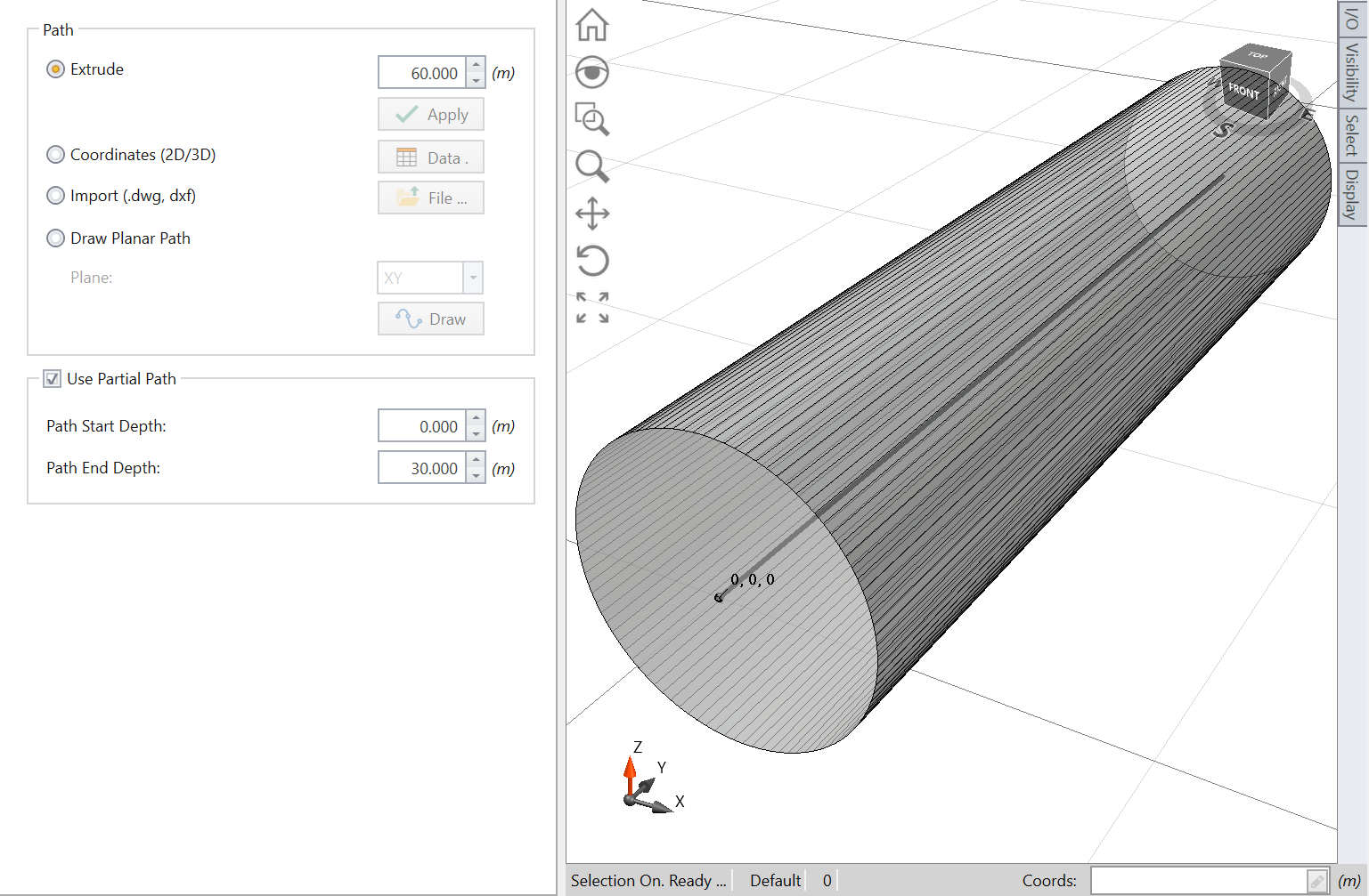
We do this to truncate the tunnel into three sections where the first path will be from 0 to 30 meters.
2.3 MULTIPLE SECTIONS WITHIN THE TUNNEL
As previously mentioned, we will be creating multiple sections of the cross-section tunnel design.
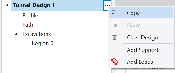
- Copy this tunnel by selecting … under Tunnel Design 1 and then select Copy. Change the name of the tunnel to Tunnel 1 Front.
- Click the + sign at the bottom of the Tunnel Designer menu, select …, and then select Paste.
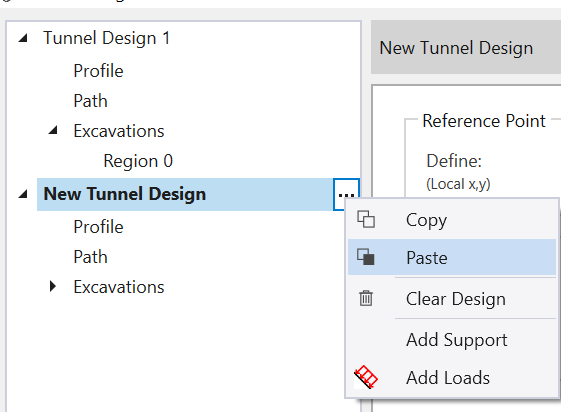
- Change New Tunnel Design to Tunnel1 X.
- Select Path and enter Path Start Depth = 30, Path End Depth = 32.
Now we will carry out the same procedure for the next three partial lengths.
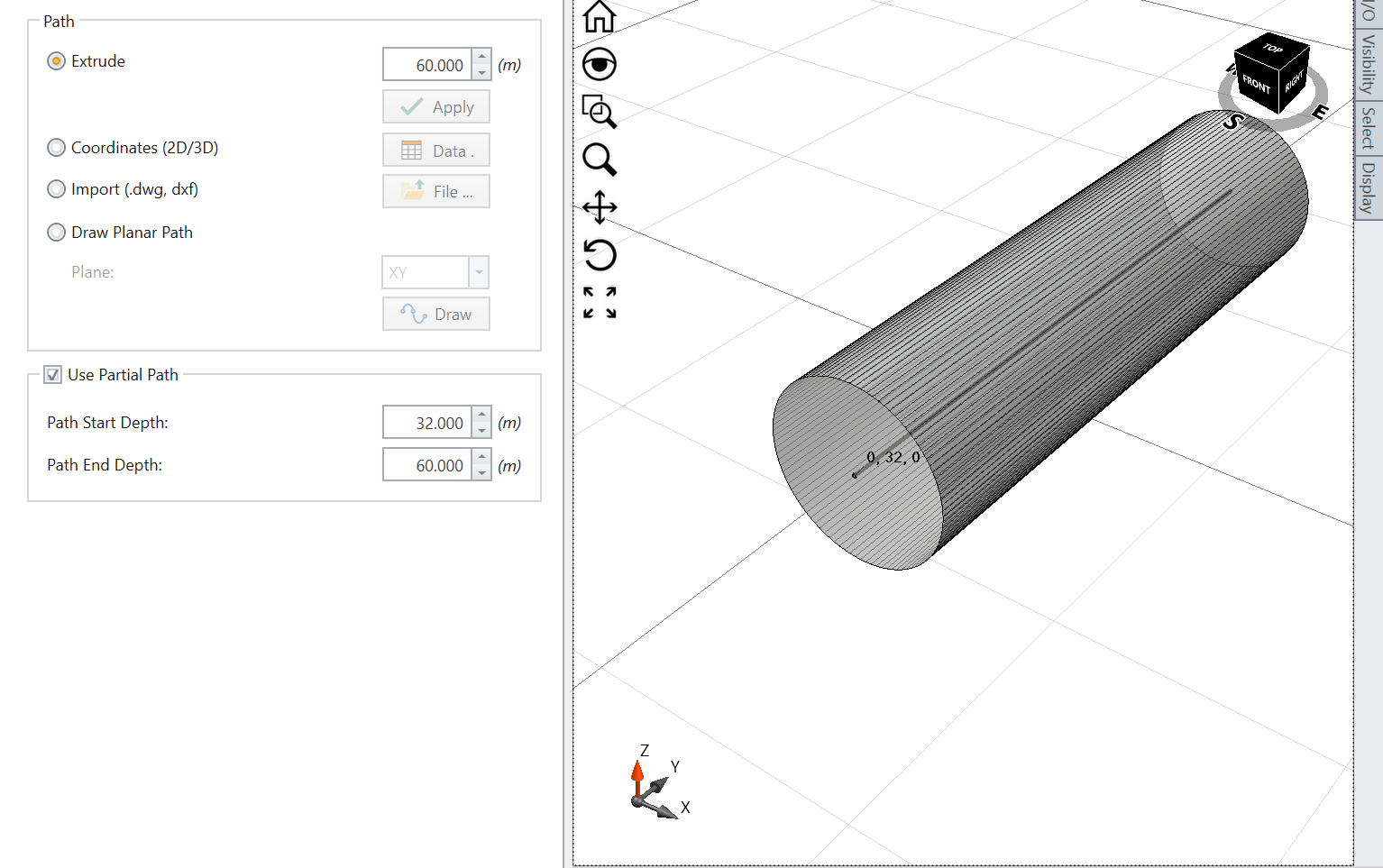
- Copy Tunnel Design 1-1 and rename the new tunnel design as Tunnel 1 Back. Then set:
- Path Start Depth = 32
- Path End Depth = 60.
2.4 CROSS-SECTION DESIGN
Now we will create the intersecting tunnel section that crosses between two circular tunnels.
- Create the new tunnel by clicking the + sign at the bottom of the Tunnel Design menu and name the tunnel Cross tunnel.
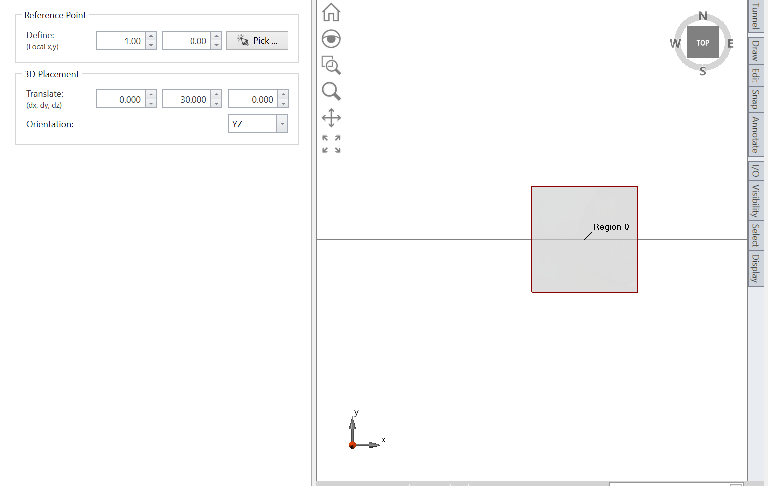
- Select: Profile > Draw > Polyline.
- Enter the coordinates as follows:
- (0, -1)
- (0, 1)
- (2, 1)
- (2, -1)
- (0, -1)
It should look similar to the image below.
2.5 ADD TUNNEL DESIGN
We will add the tunnel design to the soil model.
- Select: Tunnels > Add a Tunnel.
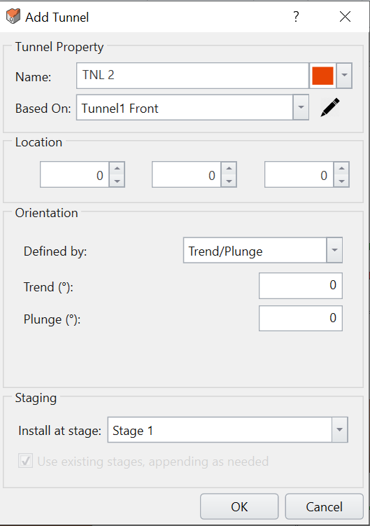
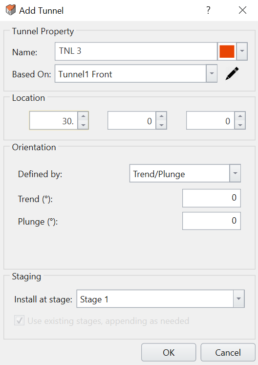
You will be prompted with this dialog. The location is already pre-defined by the coordinates we have created with partial length.
- Click OK to add Tunnel Design 1 to the soil model as shown below.
- Now continue adding the rest of the other circular tunnels along this location.You can set a staged excavation by applying each sections at different installation stages. The purpose of this tutorial, however, is more focused on the cross-section geometry of the tunnel so we will apply all the tunnels in one stage. As an additional exercise, however, you can try to assign tunnels with subsequent stages by following the procedure from the Sequence tunnel designer tutorial.
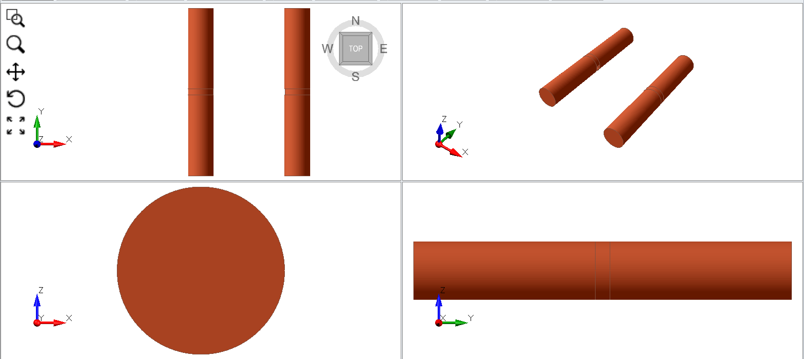
When you apply all the tunnel designs, you will see the following tunnel created as shown below (note external geometry is hidden just to show the tunnel for this image).
- Now we will apply the same tunnel that is 30 meters offset from the original location. Follow the same procedure, except now enter 30 meters in the X direction (30, 0, 0) under Location
- Apply the rest of the other tunnels with this location (30 in x-direction) for the front, middle, and back of the circular tunnel.
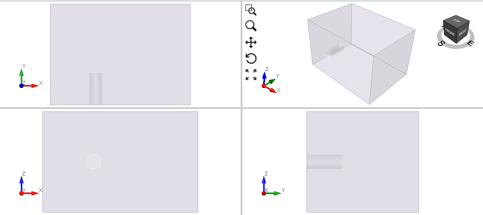
Now we will be adding a cross-section tunnel to the soil model.
- Select: Tunnels Tools > Add a Tunnel.
- The Location should be applied at (0, 31, 0) by default as shown below.
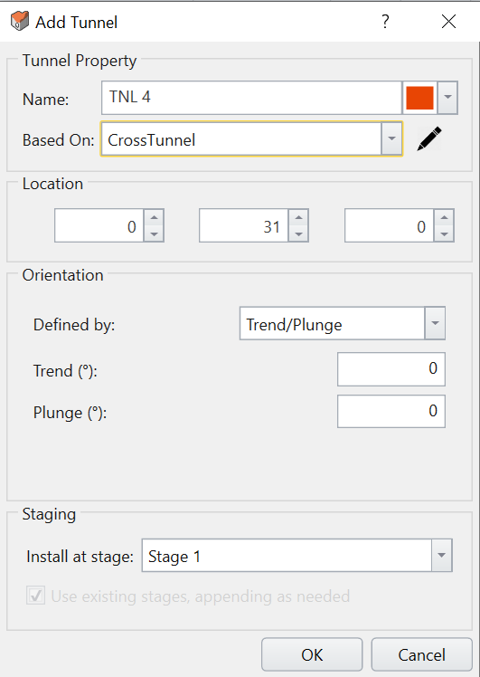
- Click OK.
2.6 CONSTRAINED DIVIDE ALL
The next important step is to divide all geometry with tunnel design applied to the soil model.
- Select: Tunnels > Constrained Divide All.
- Keep the quality to default and click OK. Your model should look like the following.
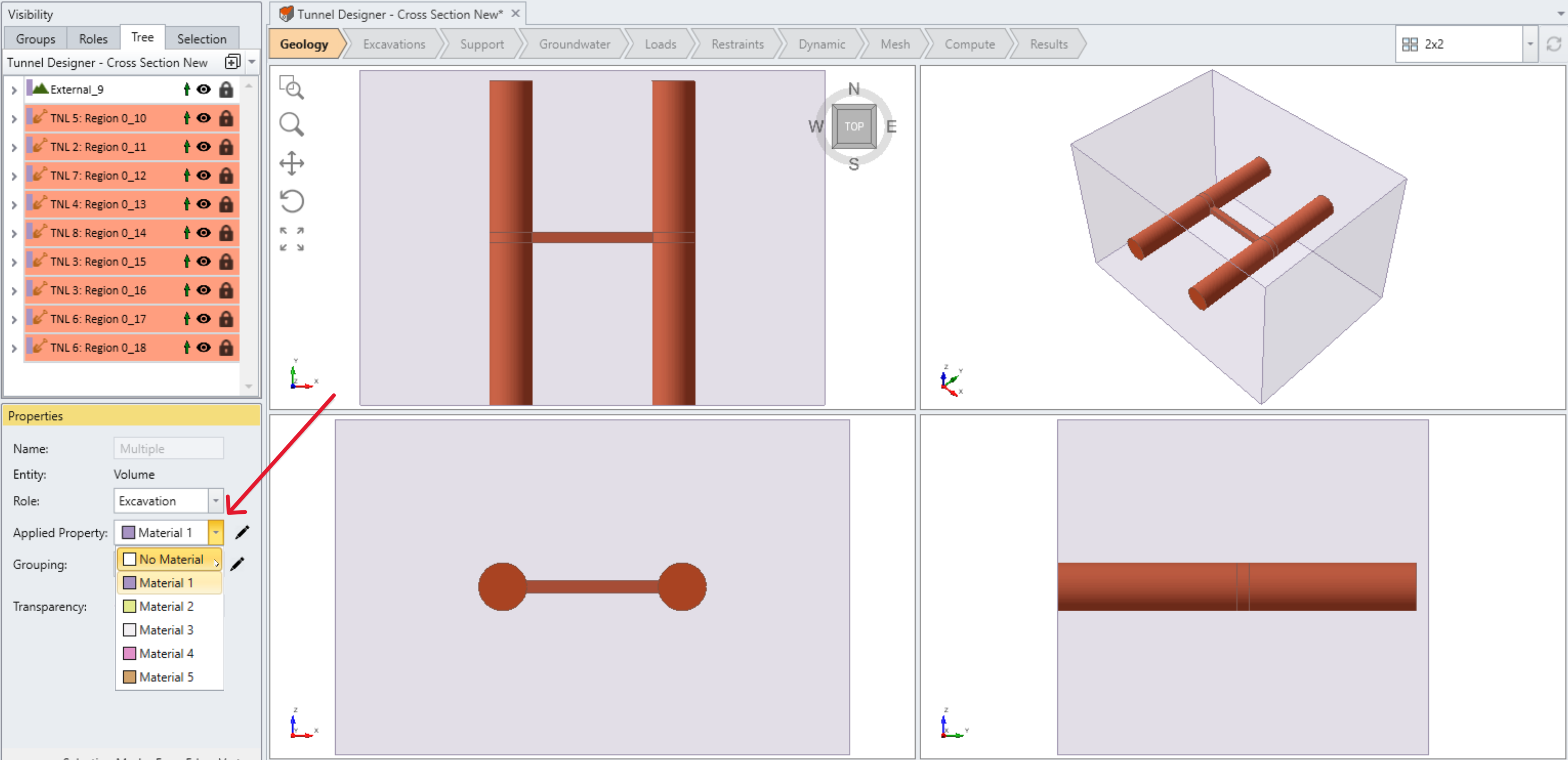
2.7 TUNNEL EXCAVATION
- Select all tunnel entities from the visibility pane
- From the properties pane, change Applied Property from Material 1 to No Material
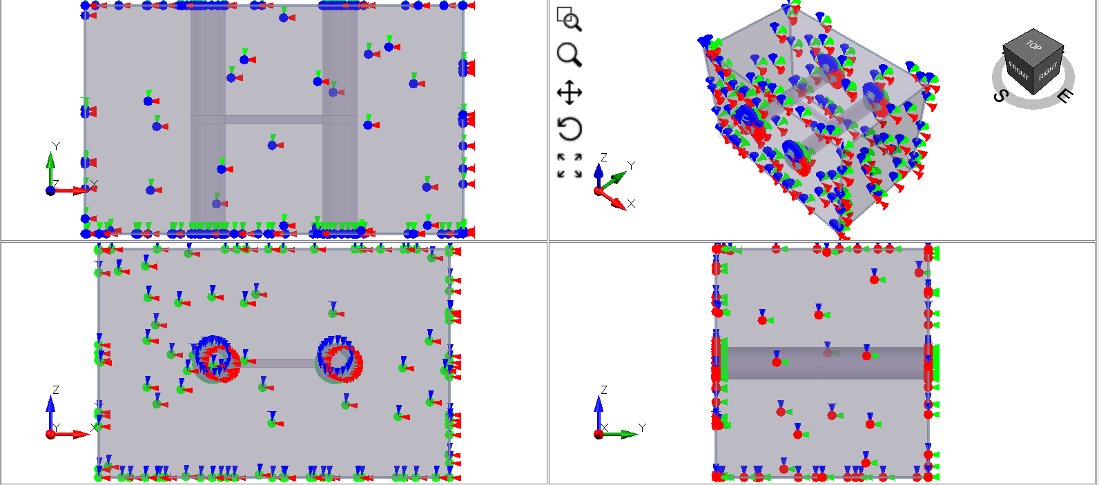
3.0 Restraints
- Select the Restraints workflow tab.
- Select: Restraints > Auto Restraint (Underground).
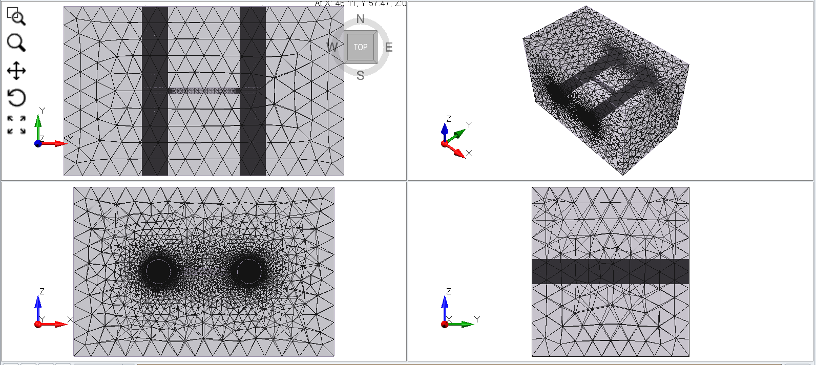
4.0 Mesh
- Select the Mesh workflow tab.
- Select: Mesh > Mesh.
5.0 Compute
Make sure that all the tunnels are excavated before compute. You can check the settings by selecting edit in the properties pane when you select the tunnels.
- Select the Compute workflow tab and click Compute

6.0 Results
- Select the Results workflow tab.
- In the menu, select Interpret > Show excavation contour.
- Make sure the exterior contour option is hidden so that the visibility tree pane to see the excavation contour option more clearly.
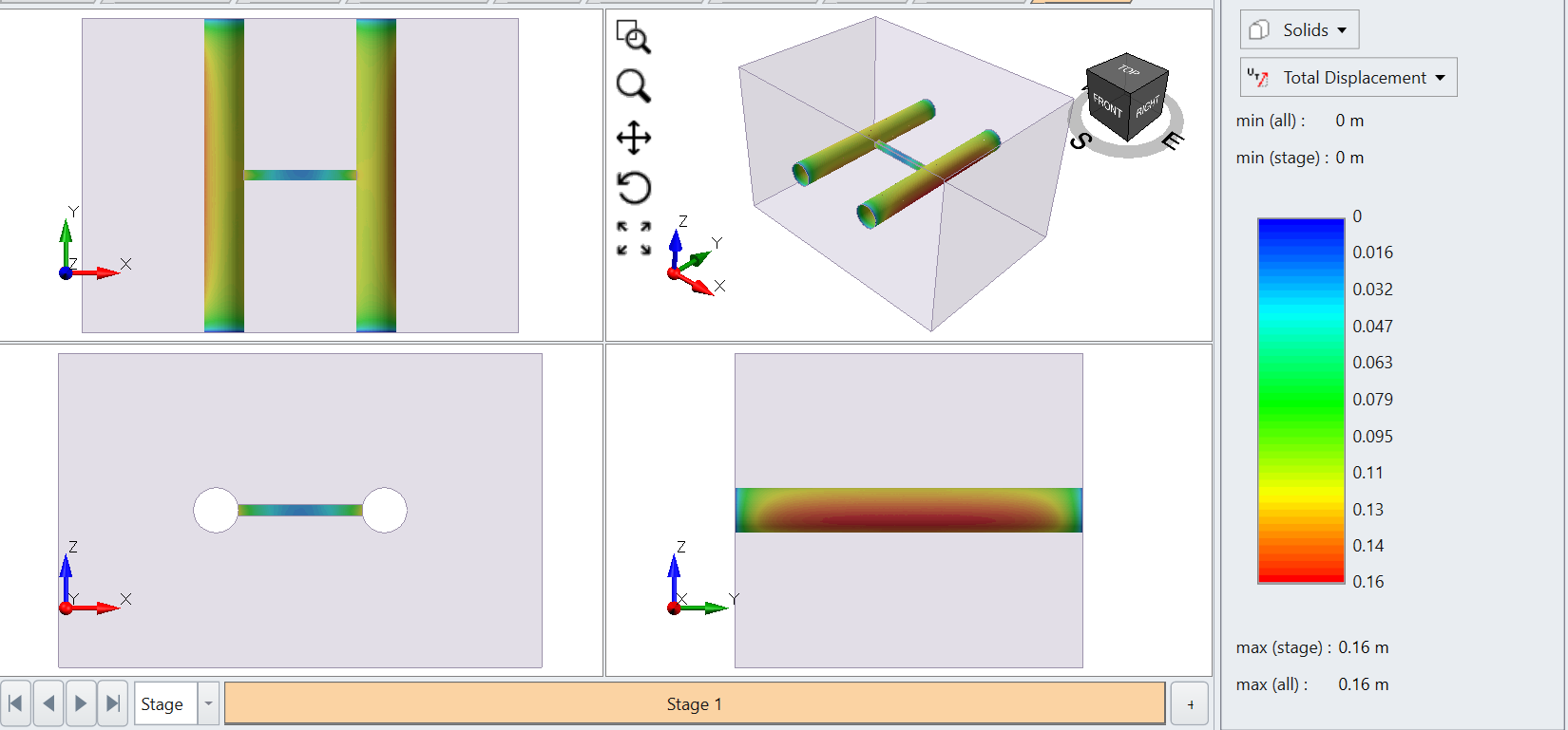
We will first look at the total displacement of the excavation.
- Select Solids > Total displacement on the contour option shown on the right side of the program.
Now let’s examine the stresses at the tunnels.
- Select Solids > Total mean stress.
- Note that you can hide the external box around the model by selecting the eye icon in the visibility tree to turn off the layer.
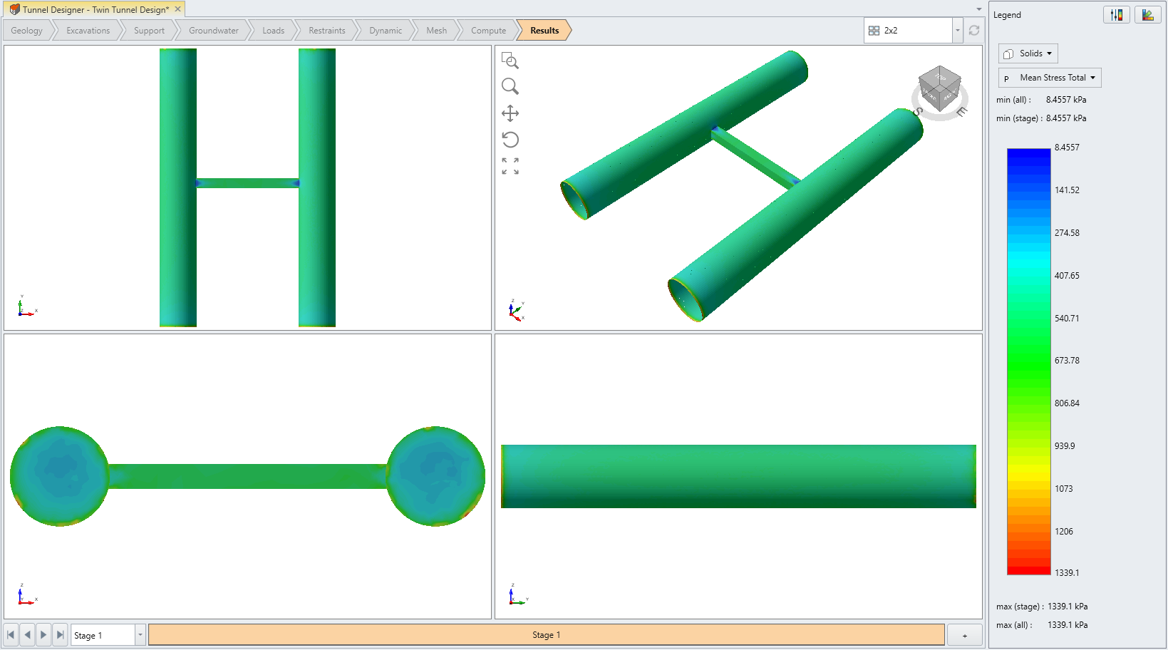
The excavation shows higher stress at the corners of the crossing and at the surface of the excavation. This allows you to visualize and apply supports where you would be expecting higher stress concentration at the excavations of cross tunnels as shown in the model.
This concludes the tutorial.