Add Lining
The Add Lining option allows you to apply liners to the faces of External geometry. In RS3, liners are added as lining sets defined with the Define Lining Composition option. A lining set can consist of one or multiple liner layers with joints (i.e., joints act as liner interfaces).
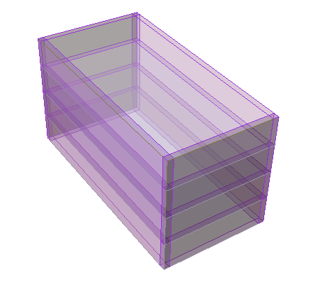
E.g., Liner (purple segments) applied to edges as sheet pile walls for an excavation:
To add a lining set:
- Select the Support workflow tab

- Select Faces Selection
 as the Selection Mode to add geometry faces to add the liner.
You can hold the SHIFT key and left click the mouse to select all connected faces. - Select Add Lining
 from the toolbar or Select: Support > Liners > Add Lining. You will be prompted to a dialog.
 - In the Add Lining dialog, select a lining set from the Lining Property dropdown list.
- To edit the lining set, select the edit
 option. You will be prompted to the Lining Composition dialog to modify the order and staging of liner layers. See the Define Lining Composition topic for more details.
- To further edit the properties of a liner layer, select the pencil icon in the Lining Composition dialog. You will be prompted to the Liner Properties dialog. See the Define Liner Properties page for more details.
- To further edit the properties of a liner layer, select the pencil icon
- To edit the lining set, select the edit
- The Flip Orientation option allows you to change the direction of the lining set. See the Flip Orientation section below for more details.
- You can stage the liner installation using the Install at stage and Remove at stage options.
See below for details about using the Auto-remove in excavated material option. - When you are finished selecting, press OK.
- Liners are now added as lining sets to the model. They are represented by thick coloured surfaces displayed on the applied faces of the geometry. The colours correspond to each liner layer are defined in the Define Liner Properties dialog (Step 4).
If liners are not initially installed at the desired stage, or with the desired property type, the staging and property type can be changed at any later time using the edit options. See the Edit or Delete Liners topic for more information.
Flip Orientation
The Flip Orientation option allows you to flip the liner orientation by 180 degrees.
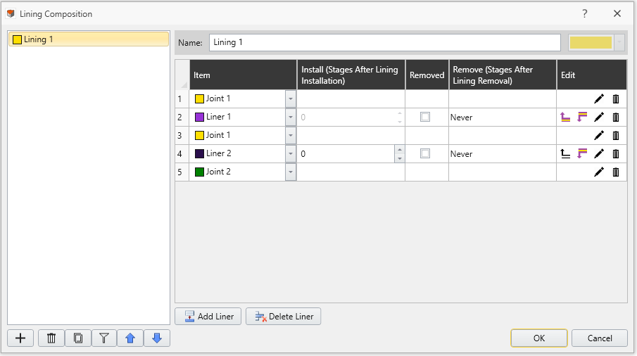
Before Add Lining option, the order of liner layers has been specified with the Define Lining Composition option (see Figure 2 below).
With the Add Lining option, the Flip Orientation option is off by default, where lining set components will be layered normal and inward to the selected surface (see Figure 3a below). However, the liner orientation may sometimes be opposite from the intended direction (i.e., 180 degrees off). For such cases, you can select the Flip Orientation checkbox, so that the liner will be placed normal but outward to the selected surface (see Figure 3b below). See Figure 3a-3b with Flip Orientation checkbox on and off.
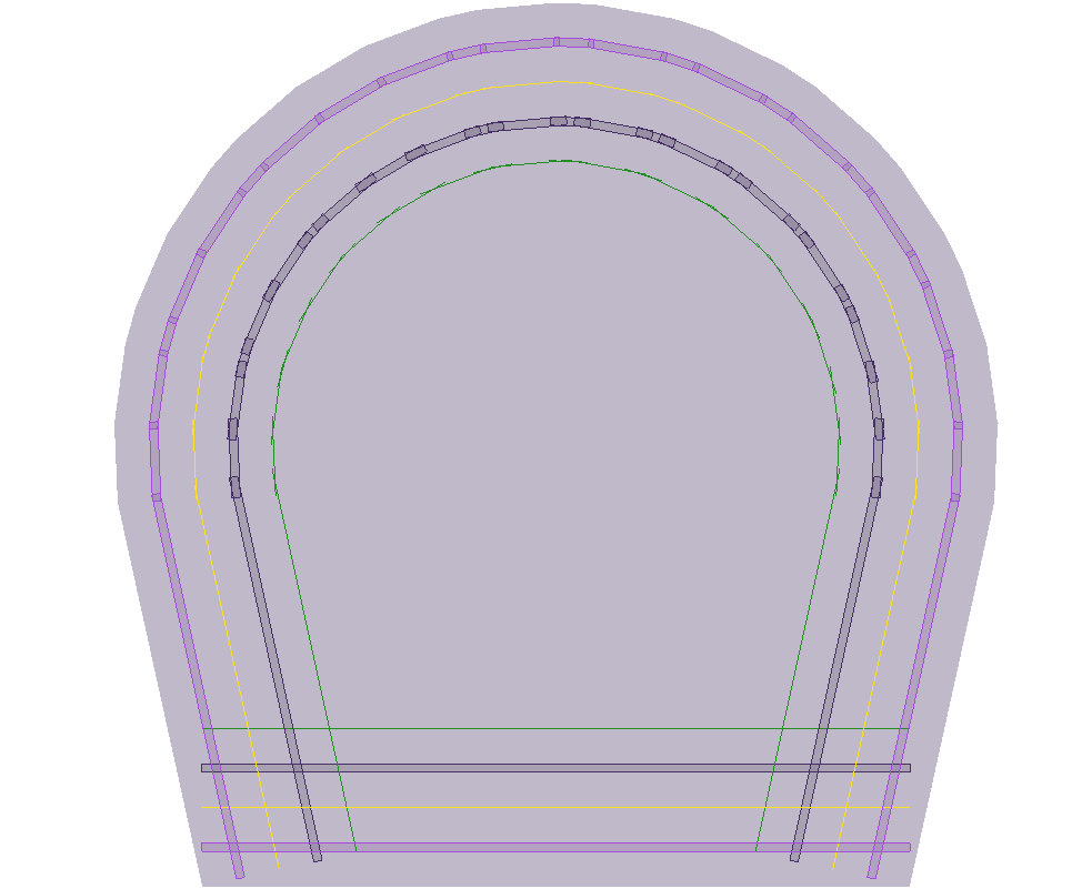 | 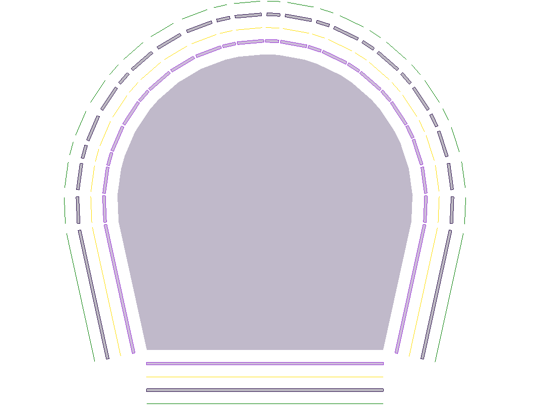 |
To view the full lining composition as shown in Figure 3a-3b above, you can use the Expanded View option in the Properties panel. See the Display of Lining Composition section in the Define Lining Composition topic for more details.
Staging
If your model is staged, you can specify the installation (and removal) stage of a liner.
- Install at stage - by default the installation stage will be set to the stage that you are currently viewing (i.e. the currently selected stage tab). You can enter a different stage if necessary.
- Remove at stage - (optional) you can also specify a removal stage, by selecting the Remove at stage checkbox and entering the stage at which the liner is to be removed (uninstalled).
Auto-remove in excavated volume
If a liner is applied to a boundary, and then the material on BOTH sides of the boundary is excavated at a later stage, the liner can be automatically removed by selecting the Auto-remove in excavated volume checkbox. If this checkbox is NOT selected, then liners which span an excavated volume will remain in place (which could be used to model struts or trusses for example).