Discontinuity Surface
Discontinuity Surface is used to model the direction and extension of fractures, wavy discontinuities and faults. Discontinuity Surfaces can be assigned to Trace measurements. The modelled surface is defined by trend and plunge whereas the parameters are derived from the orientation of the initial Trace measurement. If the originating Trace has not enough variation on depth no orientation in provided and the direction of the Discontinuity Surface is obtained derived from the current view . After first generation, Discontinuity Surfaces can be adjusted individually by the user in terms of trend, plunge and extension.
Standard operating procedure
- Select Trace from the Structure List or the 3D model using the left mouse button
- Click on the “Add Discontinuity Surface”
 icon or use the shortcut key “S”. The feature is also available in the context menu of the individual measurements. The trend, plunge and extension of the Discontinuity Surface is displayed instantly in the Structure List.
 - Adjust the settings of the Discontinuity Surface in the Properties pane.
The below figure shows the Properties pane for Discontinuity Surfaces. The pane is activated in the context menu with “Show Properties” or by a click on “Windows | Properties” in the menu bar. It comprises the name of the Discontinuity Surface, information to which Structure Set the Discontinuity Surface belongs and the “Reset” and “Project from View” button. In addition, the orientation (trend and plunge) and the extension modelled surface is given. The name, orientation and extension parameter(s) can be edited.
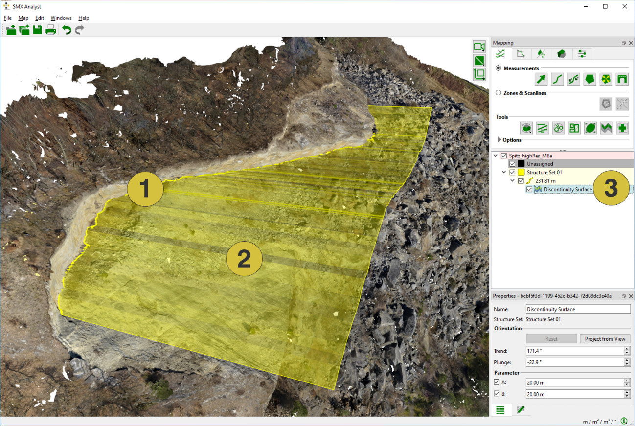
- Trace
- Discontinuity Surface based on the Trace
- Discontinuity Surface in the Structure List
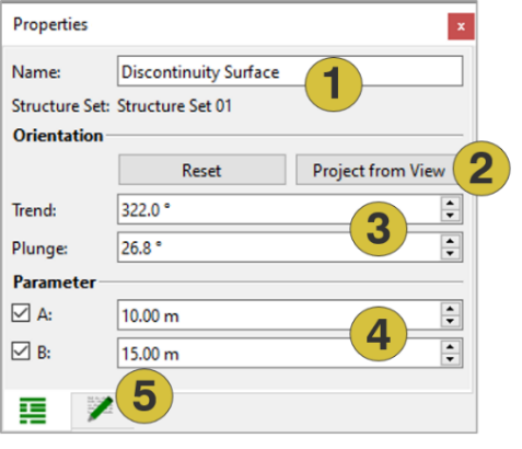
- Name of the Discontinuity Surface (editable), Structure Set and data source
- Retrieves original settings / Modifies orientation in respect to the current view
- Adjustment of trend and plunge (editable)
- Adjustment of extension (editable)
- Notes (editable)
Discontinuity Surfaces can be edited if they are selected with a click with the left mouse button on the entry in the Structure List or on the display in the 3D viewer. Selected Surfaces are highlighted in the Structure List with a shaded background and with the boundary curve in the 3D viewer. Editing of Discontinuity Models is performed in the Properties pane (see above).
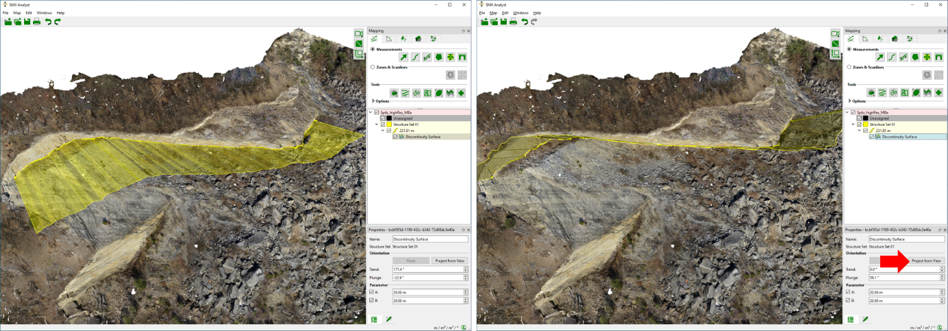
Changing the orientation of a Discontinuity Surface is possible in two modes:
- Trend/Plunge
The orientation of a Discontinuity Surface can be adjusted by trend and plunge by entering new the desired values in the corresponding fields - Project from View
The surface is projected from the current view in the 3D viewer
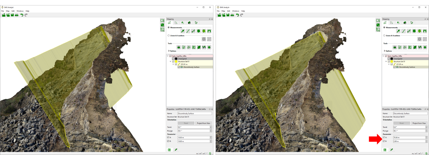
The extension of Discontinuity Surfaces can be modelled by changing the A parameter (in direction of the orientation) and B parameter (180° against the orientation) in the properties pane (see below).
Context menu
- Project from View
Projects the direction of the surface in respect current view in the 3D viewer - Reset
Resets the orientation to the originating value - Set Colour
Allows changing the colour of a Discontinuity Surface - Active
- Look at
Centers the Discontinuity Model Surface in the 3D viewer - Look at and Zoom
Centers and zoom the Discontinuity Surface in the 3D viewer - Delete
Deletes the selected Discontinuity Surface - Show Properties
Opens the Properties pane for the Discontinuity Surface - Export
- Exports Discontinuity Surface as DXF Exports the Discontinuity Surface as “.dxf” mesh