Scanline
The Scanline is a Structure Tool directly related to geological data evaluation. It is a line along the surface defined by two points identifying the intersections with Traces and Areas, calculating the distances between the intersections and providing statistical data on the joint spacing along the Scanline. Scanlines appear as a blue dashed lines in the 3D viewer and are managed in an individual list (called Scanlines) in the Structure tab of the Mapping pane. If the Scanline entry is selected in the list intersection points between the Scanline and Traces/Areas are highlighted in the 3D viewer.
Standard operating procedure
- Activate “Zones & Scanlines” in the toolbar of the Structure tab by clicking the corresponding radio button
- Click on the “Scanline”
 icon in the toolbar or use the shortcut key “S”
 - Mark the start point of the Scanline with a left button mouse click
- Mark the end point of the Scanline with a left button mouse click
- Finish the Scanline and add continue the mapping by pressing the “Space” key or finish the Scanline by clicking “Enter” or by clicking the “Scanline” icon. The Scanline is displayed instantly in the corresponding list in the Structure tab.
Edit the Scanline measurement by a double click with the right mouse button on the item and set a new start and/or end position of the Scanline measurement by clicking the left mouse button. The point closer to the mouse cursor is affected.
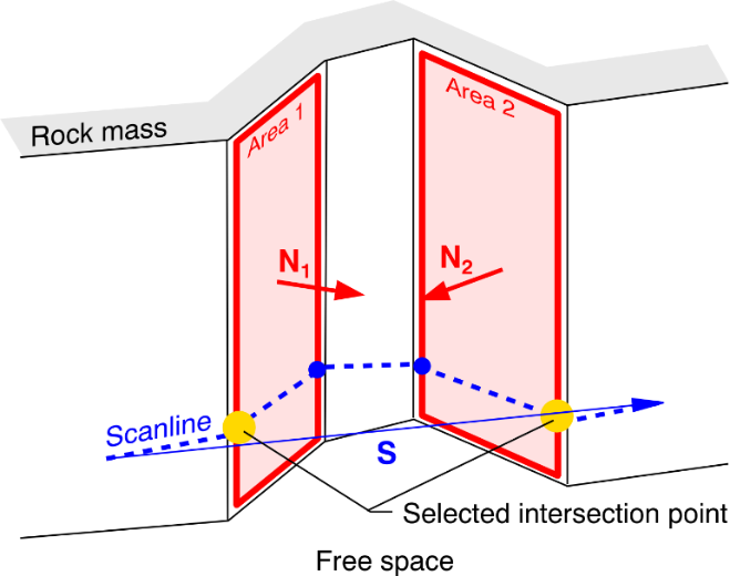
Traces and Areas are used to calculate the spacing values for Set Spacing, Normal Set Spacing, and Total Spacing. The Scanline determines all intersection points between Traces and Areas. The relevant intersection point of a Scanline and a particular structure is determined according to the relative orientation of the structure to the Scanline. Spacing values are based on the distances between intersection points. If the structure's spaceside normal vector (e.g. N1) (the normal vector which points towards the free space) points in the same direction as the scanline vector S, the first intersection point is chosen. If the structure's spaceside normal vector (e.g. N2) points in the opposite direction as the scanline vector S, the last intersection point is chosen.
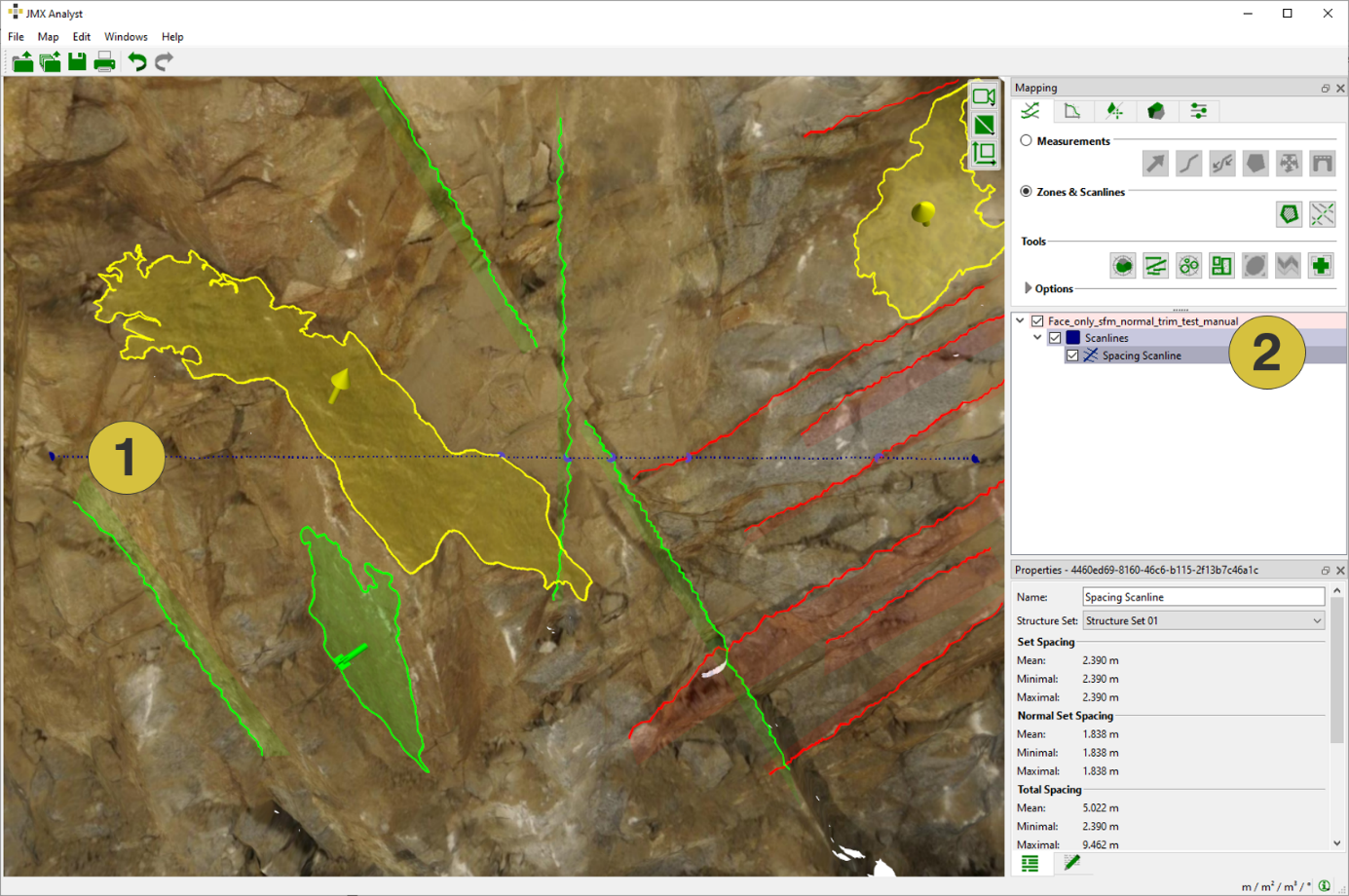
- Scanline
- Scanline listed in the Structure tab
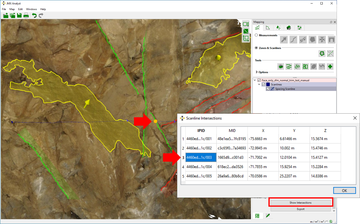
The below figure shows the Properties pane of Scanlines. The pane is opened in the context menu with “Show Properties” or by a click on “Windows | Properties” in the menu bar. It comprises the name of the Scanline. The name is editable in order to provide a descriptive name. Spacing statistics can be displayed from the entire Map or from individual Structure Set (selected in the pull down menu). Independent of the selection the dialog reveals spacing parameters obtained from individual Structure Sets (Set Spacing, Normal Set Spacing) and from the entire Map (Total Spacing). In addition the trend and plunge of the vector (defined as the vector between start and end point) of the Scanline is given and the number of intersections (in the selected Structure Set and overall Map). The Scanline Intersection dialog is opened by clicking “Show Intersections” button in the Properties pane. The dialog is also available via the context menu. It reveals intersection point co-ordinates. If an intersection point is selected in the Scanline Intersection dialog, the corresponding point on the 3D model is highlighted as a yellow sphere. Scanline data is exported to “.csv” by clicking the “Export” button. Customized notes can be added to individual Scanlines in the Notes tab.
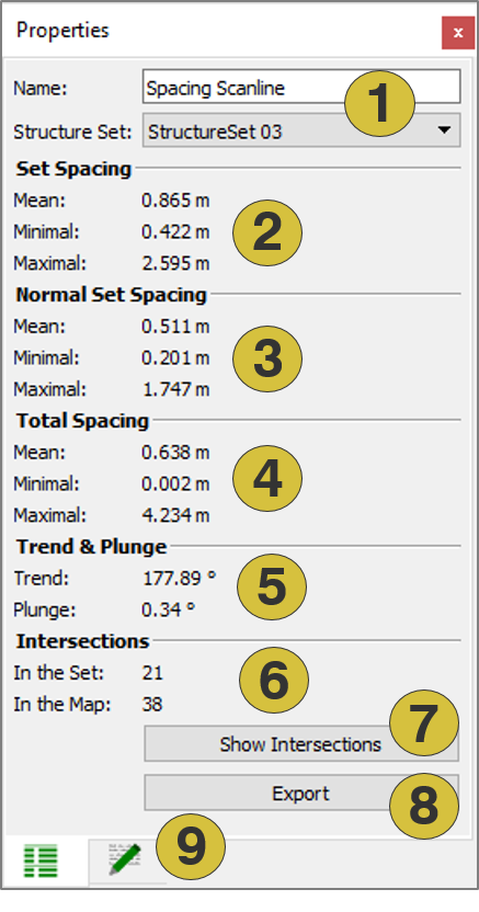
- Name of the Scanline and Structure Set (editable)
- Set spacing
- Normal set spacing
- Total spacing (entire Map)
- Trend and plunge of the Scanline
- Intersections in set and in Map
- Show intersection points
- Export spacing data
- Notes (editable)
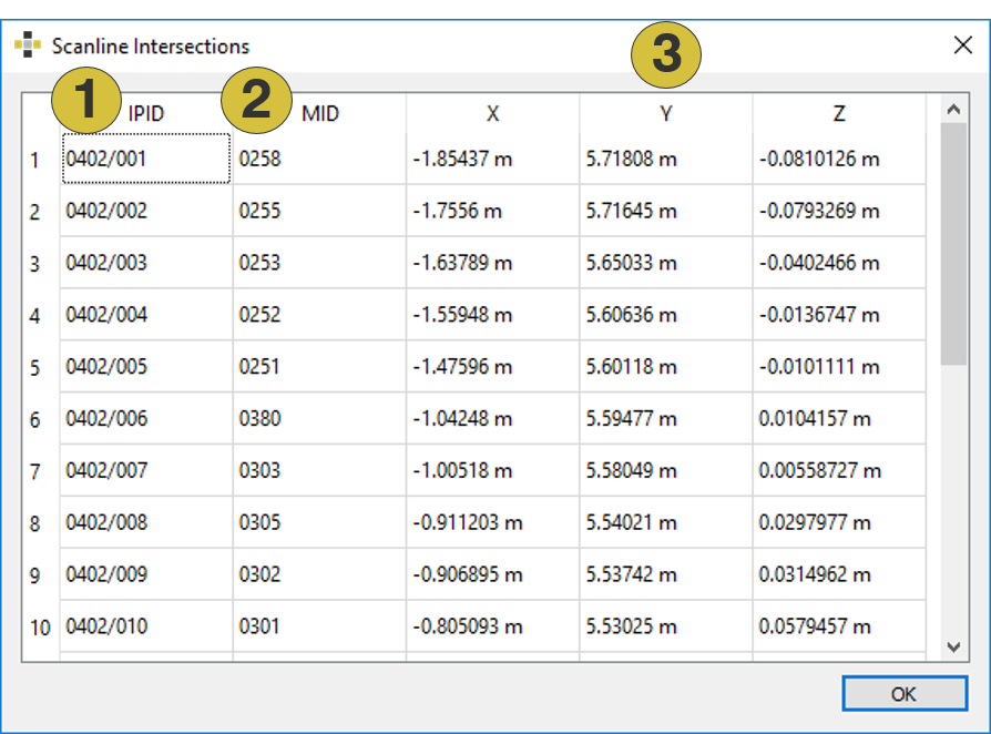
- Identification of the Scanline intersection point (IPID)
- Measurement identification (MID)
- Intersection point co-ordinates (x,y,z or E, N, H)
Context menu
- Edit
Moves one of the end points of the Scanline to a new position defined by a click with the left mouse button. The point closer to the mouse cursor is affected. - Show intersections
Opens the Scanline Intersection dialog - Active
Activates (shows) and deactivates (hides) the selected item. - Look at
Centers the Scanline in the 3D viewer - Look at and Zoom
Centers and zoom the Scanline in the 3D viewer - 3D View-dependent Redraw
Redraws the Scanline in subject to the current view - Delete
Deletes the selected Scanline - Show Properties
Opens the Properties pane for the Scanline - Export
- Export Scanline Data as CSV Exports the Scanline as “.csv” file
- Export as DXF Exports the Scanline as ”.dxf” file
- Export as VRML Exports the Scanline as ”.vrml” file