Area
The Area mode is used for annotating area based structures (e.g. discontinuity surfaces) or for regions of common geological attributes. An Area consists of a closed polygonal line that follows a discontinuity surface or any arbitrary portion of the surface . The size of the Area is provided in terms of the rough area in the Structure List. Areas are also used to determine the spacing of a Structure Set.
Standard operating procedure
- Activate “Measurements” in the toolbar of the Structure tab by clicking the corresponding radio button
- Click on the “Area”
 icon or use the shortcut key “A”
 - Map the border line of the Area on the 3D model by clicking the left mouse button. A polygonal line grows instantaneously. Undo the last action by pressing the right mouse button (multiple uses possible).
- Finish the Area measurement and continue the mapping by pressing the “Space” key or finish the Area measurement by clicking “Enter” or by clicking the “Area” icon. The Area is automatically closed, shaded and the orientation is added; i.e. mean Orientation of the surface normal. The size of the Area is provided in terms of the rough area in the Structure List.
Edit the Area measurement by a double click with the right mouse button on the item:
- Insert a point by holding “Ctrl” and clicking the right mouse button
- Delete a point by holding “Alt” and clicking the right mouse button
- Open the area by holding “Alt” and clicking the right mouse button and a click on the polygon
- Move a point by holding “Shift” and clicking the right mouse button
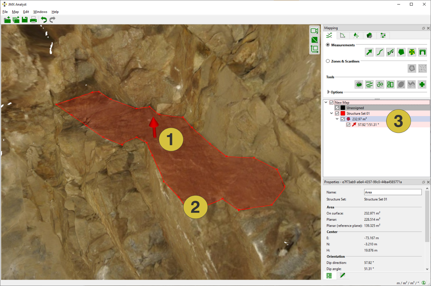
- Mean upward normal vector of the Area
- Clicked polygon follow the surface of the 3D model
- Size of Area (rough) with assigned mean dip direction and dip angle in the Structure List
The below figure shows the Properties pane of Areas. The pane is opened in the context menu with “Show Properties” or by a click on “Windows | Properties” in the menu bar. The pane comprises the name of the Area, information to which Structure Set the measurement belongs and the type of Area. In addition the (rough) size the planar size, the orientation of the joint plane (if determined), the co-ordinates of the centroid, roughness, fracture mode and the growing distance is given. The name of the Areas can be edited in order to use an intuitive name or for more detailed descriptions. Customized notes can be added to individual Areas in the Notes tab.
The roughness is undefined by default. It can be defined as very rough, rough, planar, curved or polished in the Properties pane by using the corresponding pull down menu. In addition, the fracture mode is undefined by default. It can be defined as Extensional, Shear (dextral) or Shear (sinistral) in the Properties pane by using the corresponding pull down menu.
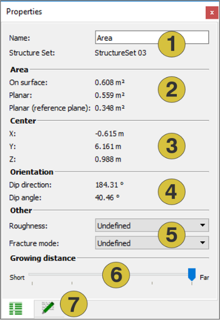
- Name of the Area (editable) and Structure Set
- Size
- Centroid
- Mean Orientation
- Roughness and fracture mode (editable)
- Growing distance (editable)
- Notes (editable)
Area size vs. planar Area size
The Area measurement provides three numbers for the area size:
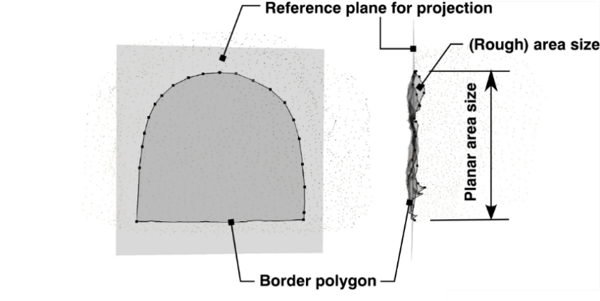
- The Area Size on Surface refers to the spatial area, i.e. the sum of triangles enclosed by the area’s polygon
- The Planar Area Size refers to the area obtained by projecting the border polygon onto a projected plane calculating the planar area enclosed by the projected polygon. The projected plane is defined by the mean plane fitted to the clicked points. The below figure gives an overview of the relationships.
- The Planar Area Size related to the Reference Plane refers to the area obtained by projecting the border polygon onto the Reference Plane calculating the planar area enclosed by the projected polygon. The Reference Plane is automatically defined by the software when generating the 3D model (“.jm3x”).
Context menu
- Edit
Insert a point by holding “Ctrl” and clicking the right mouse button. Open the Area holding “Alt” and clicking the right mouse button. Move a point by holding “Shift” and clicking the right mouse button. - Edit (Region Grow)
Adds a Growing Region to the existing Area - Reduce Points
Reduces the number of clicked points of the polygon. This is useful when modifying automatically determined areas with the region grow. - Add an Orientation
Adds a subordinate orientation to the Area. This orientation forms part of the Area measurement and has only restricted possibilities for modification. Only one orientation can be added to an Area. - Add Discontinuity Model
Models the extent of a fracture by a finite plane - Set Colour
Defines a new colour for the Area - Active
Activates (shows) and deactivates (hides) the selected item - Delete
Deletes the selected Area - Show Properties
Opens the Properties pane for Areas - Move to
Moves the Area to another Structure Set - Look at
Centers the Area in the 3D viewer - Look at and Zoom
Centers and zoom the Area in the 3D viewer - Export
- Export Structural-geologic Data as CSV Exports the measurement as “.csv” file
- Export as DXF Exports the measurement as ”.dxf” file
- Export as VRML Exports the measurement as ”.vrml” file