Discontinuity Model
Discontinuities are used to model the extent of a fracture. A Discontinuity Model in Analyst is a finite subset of a plane bounded by a defined planar curve, the bounding curve. The plane of a Discontinuity Model is defined by a position (three co-ordinates) and orientation (normal vector, or dip direction and dip angle, and an in-plane angle depending on the discontinuity shape). These parameters are taken from a Trace, Area (each of which having an orientation) or a single Orientation measurement. The user chooses the shape, orientation and position of the bounding curve. The software proposes a bounding curve after generation which aims to approximate the corresponding Area or Trace. In case of generating a Discontinuity Model based on a single Orientation, standard values for the discontinuity size are chosen (radius 1 m, A 2 m, B 1 m, Epsilon 0°).
Standard operating procedure
- Select one Orientation, Trace or Area from the Structure List or the 3D model using the left mouse button
- Click on the “Add Discontinuity Model”
 icon or use the shortcut key “D”. The feature is also available in the context menu of the individual measurements. The orientation of the Discontinuity Model is displayed instantly in the Structure List .
 - Adjust the settings of the Discontinuity Model in the Properties pane.
Edit the Discontinuity Model by a double click with the right mouse button on the item:
- Set a new positon by clicking the left mouse button
- Move Discontinuity Model on Plane by holding “Shift” and clicking the right mouse button
- Shift the Discontinuity Model by holding “Shift” and turning the mouse wheel
Discontinuity Models can only be moved if they are unlocked.
By default, Discontinuity Models have the same colour as the corresponding Annotation Element. Recolouring of Discontinuity Models is performed in the context menu by a click on “Set Colour.”
The below figure shows the Properties pane for Discontinuity Models. The pane is activated in the context menu with “Show Properties” or by a click on “Windows | Properties” in the menu bar. It comprises the name of the Discontinuity Model, information to which Structure Set the Discontinuity Model belongs and the “Unlock” and “Reset” button. In addition, the orientation, the shape, the size and other shape parameters of the modelled discontinuity is given. The name and the shape parameter(s) can be edited in any case. The in-plane angle Epsilon can only be edited for rectangles and ellipses. The orientation can only be edited if the Discontinuity Model is unlocked.
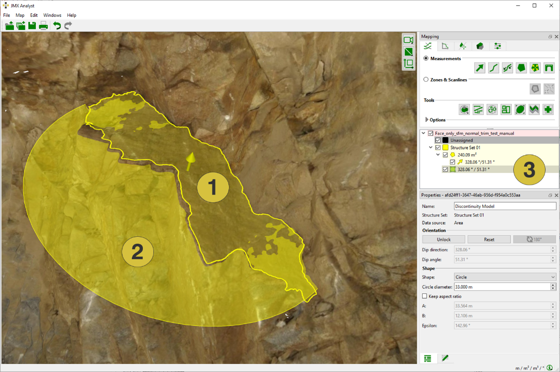
- Area
- Discontinuity Model based on the Area
- Discontinuity Model and Area in the Structure List
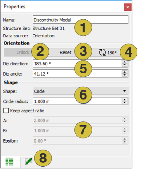
- Name of the Discontinuity Model (editable), Structure Set and data source
- Unlocks the Discontinuity Model from the Structure Measurement
- Retrieves original settings
- Rotate Discontinuity Model
- Orientation of the Discontinuity Model (editable)
- Selection of shape (editable)
- Shape parameter (editable)
- Notes (editable)
Editing Discontinuity Models
Discontinuity Models can be edited if they are selected with a click with the left mouse button on the entry in the Structure List or on the display in the 3D viewer. Selected Discontinuities are highlighted in the Structure List with a shaded background and with the boundary curve in the 3D viewer. Editing of Discontinuity Models is performed in the Properties pane (see above).
Changing the shape
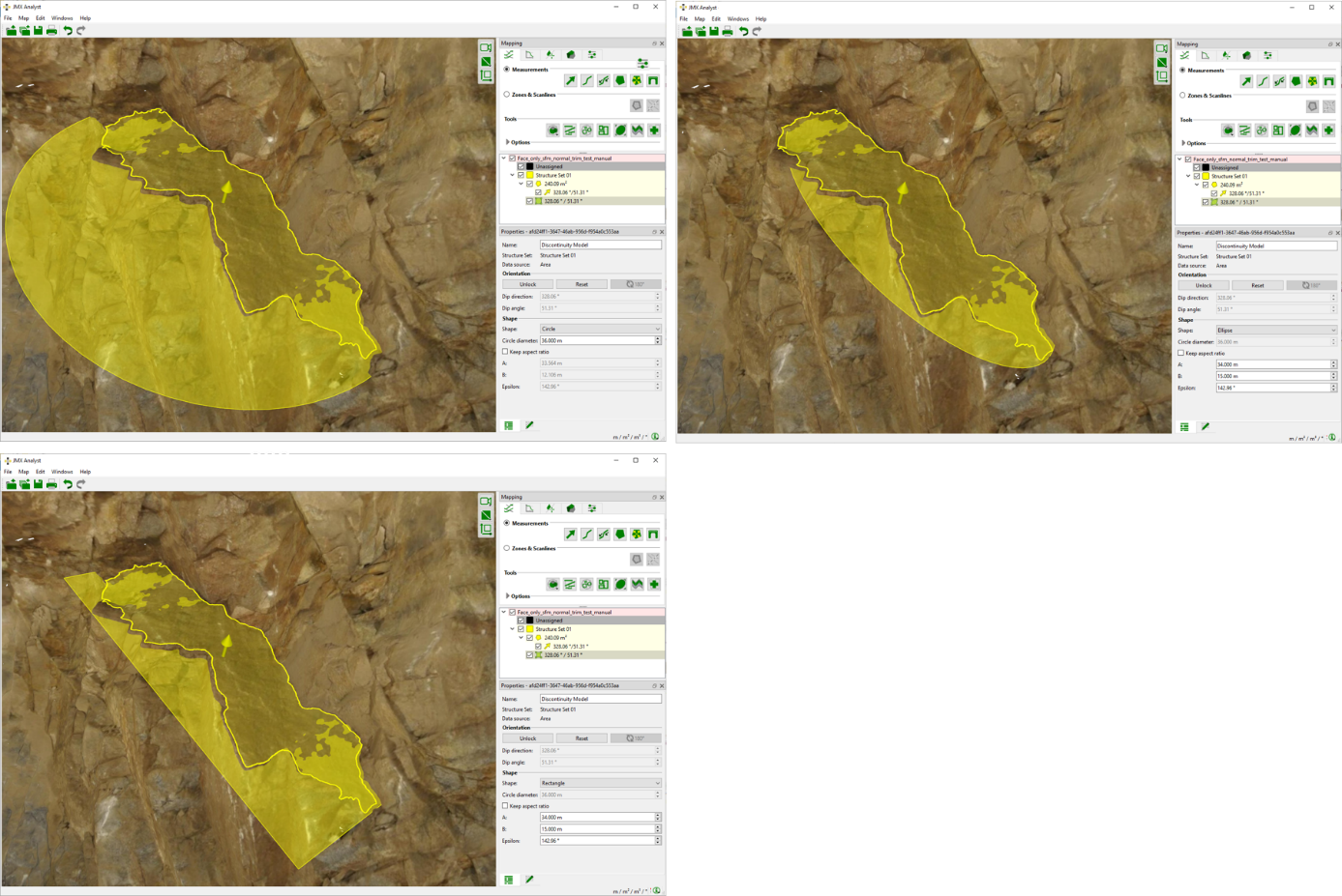
Three shapes i.e. circle, ellipse and rectangle are available (see figure below). The shape changes by clicking the pull down menu “Shape” in the Properties pane. When changing the shape also different fields of shape parameter become active. The shape can be changed for locked and unlocked Discontinuity Models.
Changing the size
The size of a Discontinuity Model is defined by:
- Circle: the radius of the circle
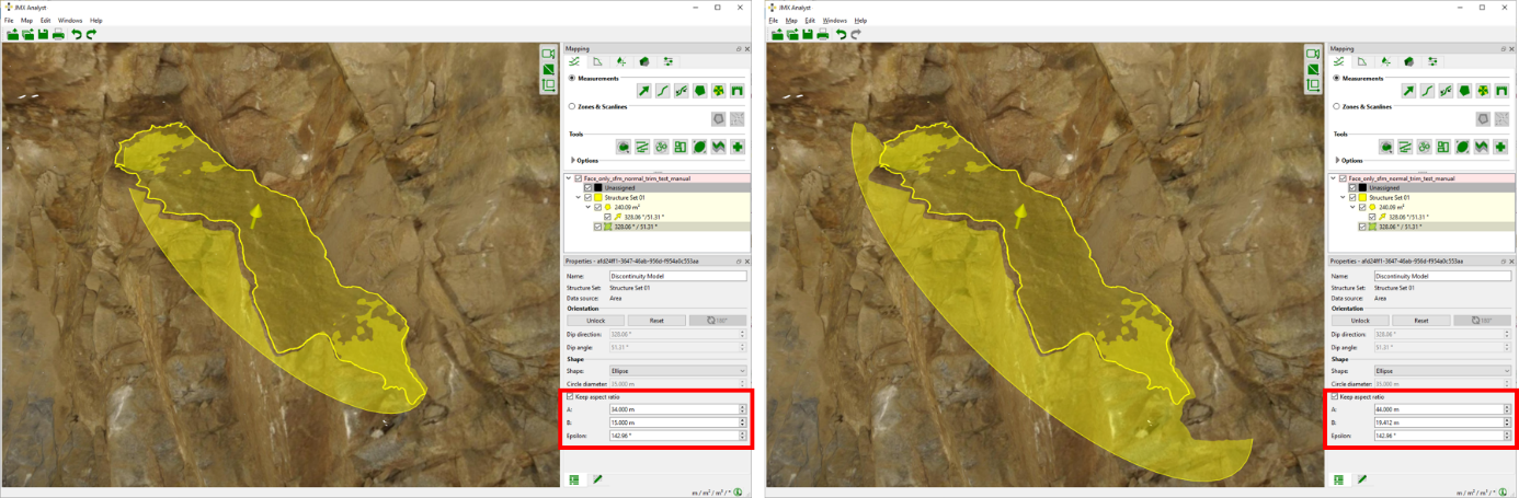
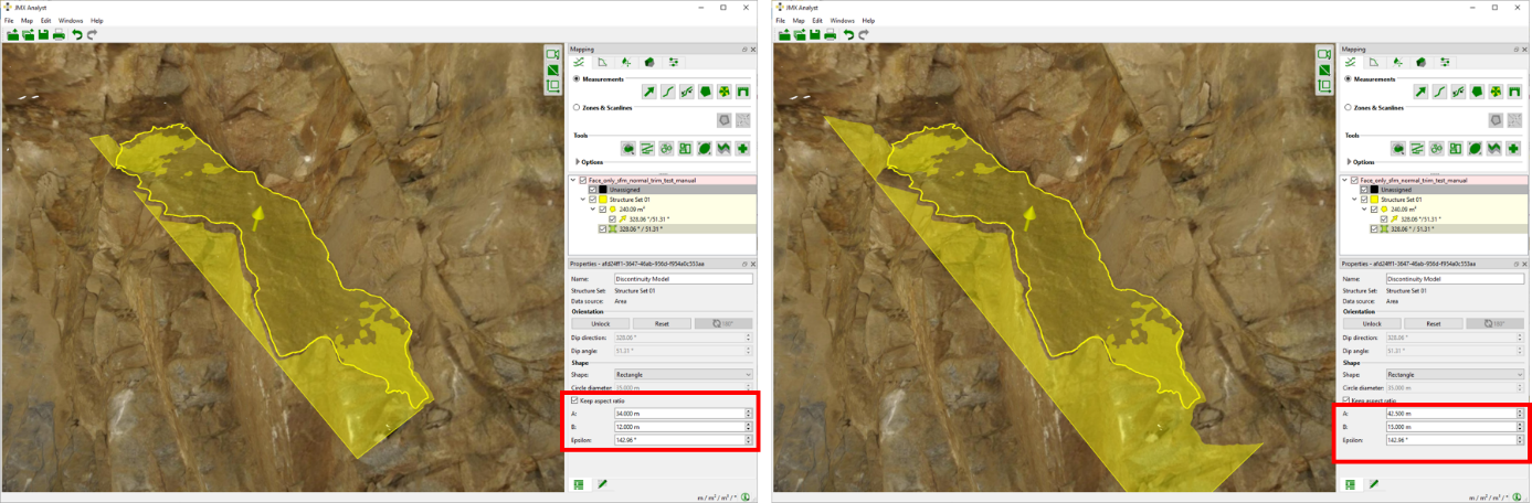
- Ellipse and rectangle: the longest dimension (A) and the shortest dimension (B)
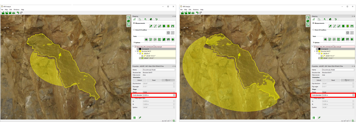
After modelling the discontinuity the software proposes the size parameters to approximate the original Trace or Area. For editing the size the desired values can be entered in the active fields (radius or A, B;) or by using the scrolling mechanism. The ratio between the values A and B can be kept constant by ticking the box “Keep aspect ratio” for ellipses and rectangles. If the box “Keep aspect ratio” is not selected, the values A and B are changed independently. The size of the Discontinuity Model can be changed if it is locked and unlocked.
Changing the orientation in the plane (epsilon)
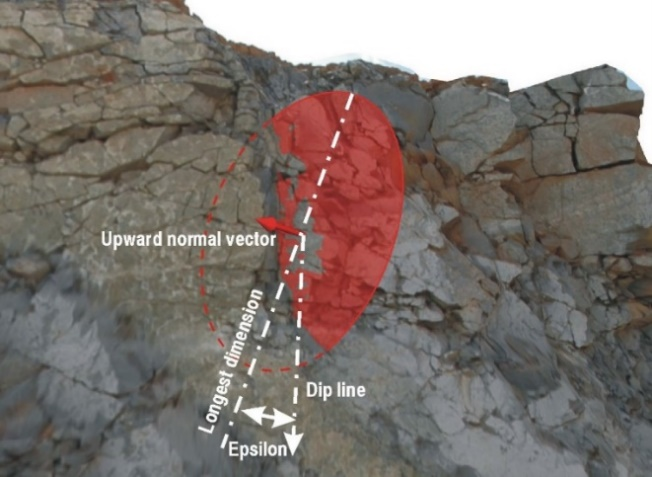
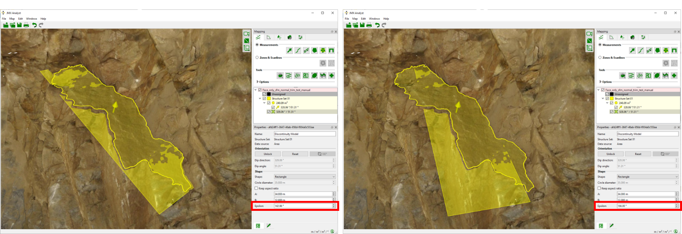
The orientation in the plane is the angle (epsilon) of the Discontinuity Model relative to the dip line. It is only relevant for ellipses and rectangles. Epsilon is measured in clockwise direction when looking towards the upward normal vector of the plane. If epsilon is zero, the longest dimension of the ellipse or rectangle corresponds to the dip line of the plane. For editing the angle epsilon the desired values can be entered in the active field (epsilon) or by using the scrolling mechanism.
Unlocking and resetting a Discontinuity Model
Discontinuity Models can be locked or unlocked. They are unlocked by clicking the “Unlock” button in the Properties pane. The locked status can be recovered by clicking on the “Reset” button in the Properties pane. Unlocking a Discontinuity Model gives the user more degrees of freedom for editing. Unlocking enables to move the discontinuity to another position and changing the orientation (dip direction and dip angle). A locked Discontinuity Model indicates the user that there were no essential changes to the plane data compared to the original Area or Trace measurement. The icon of a locked Discontinuity Model in the Structure List appears with holders. Unlocked Discontinuity Models indicates the user that there might have been essential changes compared to the original Area or Trace measurement. The icon of an unlocked Discontinuity Model in the Structure List appears without holders.
Changing the position of a Discontinuity Model
The position of a Discontinuity Model can only be changed if it is unlocked. The position is changed by moving the Discontinuity Model in the 3D viewer in the Edit mode while keeping the left mouse button pressed. Two modes are available:
- Move Discontinuity Model
The Discontinuity Model can be placed arbitrarily on the 3D model by clicking the right mouse button - Move Discontinuity Model on Plane
The Discontinuity Model can only be moved inside the original plane but on an arbitrary position by holding “Shift” and clicking the right mouse button
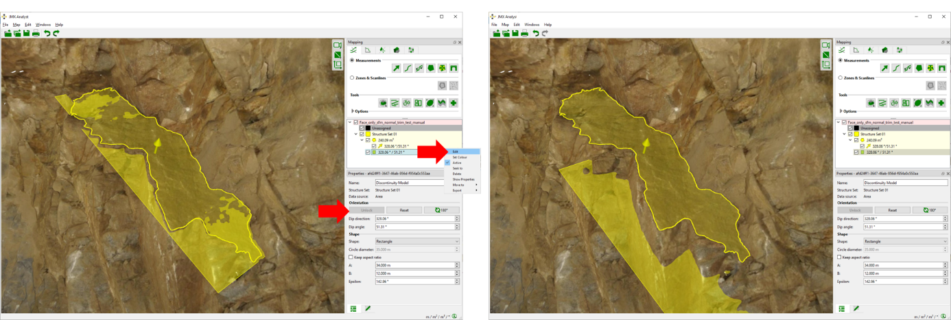
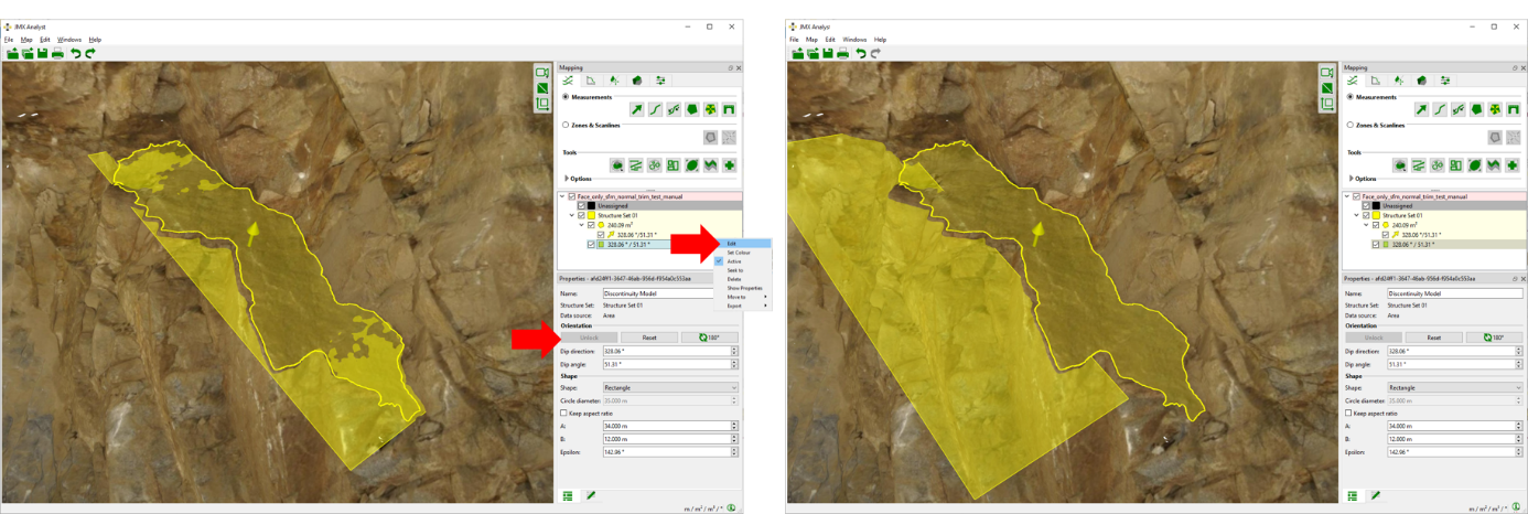
Changing the orientation of a Discontinuity Model
The orientation (dip direction and dip angle) can only be changed for an unlocked Discontinuity Model. Dip direction and dip angle can be edited in the Properties pane by entering the desired values or by using the scrolling mechanism.
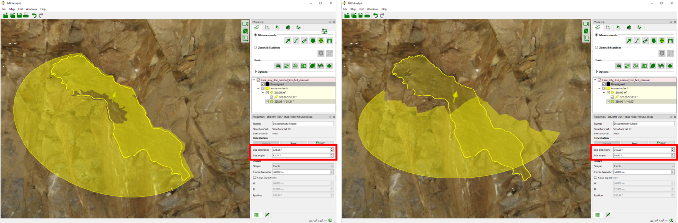
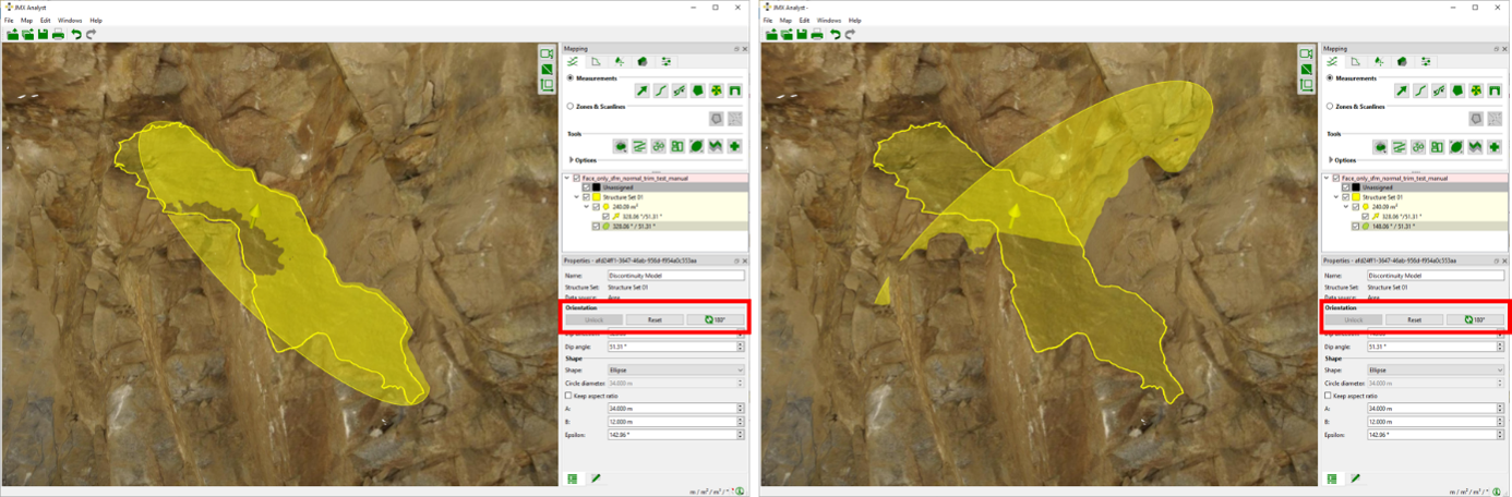
Rotate Discontinuity by 180°
Rotation by 180° can only be performed for an unlocked Discontinuity Model by clicking on the according button in the Properties pane.
Context menu
- Edit
Set a new positon by clicking the left mouse button. Move Discontinuity Model on Plane by holding “Shift” and clicking the right mouse button. Shift the Discontinuity Model by holding “Shift” and turning the mouse wheel. Discontinuity Models can only be moved if they are unlocked. - Set Colour
Allows changing the colour of a Discontinuity Model - Look at
Centers the Discontinuity Model in the 3D viewer - Look at and Zoom
Centers and zoom the Discontinuity Model in the 3D viewer - Delete
Deletes the selected Discontinuity Model - Show Properties
Opens the Properties pane for the Discontinuity Model - Move to
Moves the Discontinuity Model to another Structure Set - Export Export Options
- Exports Discontinuity Model as DXF Exports the DiscontinuityModel as “.dxf” mesh
- Exports Discontinuity Model as CSV Exports the Discontinuity Model as “.csv”
- Export as DXF Exports the Discontinuity Model as “.dxf”
- Export as VRML Exports the Discontinuity Model as “.vrml