Mapping Pane
The Mapping pane includes five tabs (i.e. Structure, Geometry, Occurrences, Area Partitioning and Settings) with tab-specific toolbars and options described below.
Structure  – Measurements
- Orientation
 - Adds an Orientation
 - Trace
 - Adds a Trace
 - Guided Trace
 - Adds a Trace by semi-automatic detection
 - Area
 - Sets the polygon of the Area boundary
 - Region Grow
 - Adds an Area by semi-automatic detection
 - Bridge
 - Adds an Bridge between two Traces
Structure – Zones & Scanlines
- Zone
 - Adds Zones (Analysis or Exclusion Zones)
 - Scanline
 - Adds a Scanline
Structure – Tools
- Region Detection
 - Detects Areas fully automated
 - Trace Map Analysis
 - Opens the Trace Map Analysis dialog for analyzing spacing and lengths of Structure Measurements
 - Stereonet Analysis
 - Plots the poles of measured Orientations in a stereographic projection
 - Clustering
 - Groups Structure Measurements into clusters
 - Add Discontinuity Model
 - Models the extent of a fracture by a finite plane
 - Add Discontinuity Surface
 - Models the direction of a fracture
 - Add Structure Set
 - Adds a new Structure Set
Geometry  – Measurements
- Volume
 - Sets the polygon of the Volume boundary
 - Area Basic - Sets the polygon of the Area Basic boundary
- Tape
 - Adds a Tape measurement
 - Measuring Point
 - Sets Measuring Points
 - Profile
 - Draws a vertical section (Profile) on the 3D model
 - Section
 - Draws a cutting plane on the 3D model
Geometry – Tools
- Contour Lines
 - Generates contour lines of the 3D model
 - Cutoff Plane
 - Splits the 3D model into two regions along a Cutoff Plane
 - Depth Colouring
 - Shows the 3D model in false colours to show irregularities of thesurface
 - CSV 4D
 - Imports Movement data from Guardian – IDS GeoRadar (“.csv”)
Occurrences 
- Water
 - Adds a Water annotation
 - Punctual Event
 - Adds a Punctual Event
 - Non-Punctual Event
 - Adds a Non-punctual Event with a polygon
Area Partitioning 
- Lithologic Region
 - Adds an Lithologic Region on the 3D model
 - Homogenous Areas
 - Adds regions of Homogenous Areas on the 3D model
Settings 
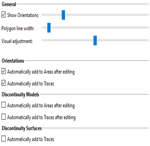
General
- Show Orientations (Object scale)
The scale of Orientations (arrows and semi-transparent joint planes) is set in this option by moving the slider - Polygon line width
The line width of polygons (e.g. Traces, Areas, Tape, etc.) is set in this option by moving the slider - Visual adjustment
The distance between drawn Annotations Elements and the 3D model can be adjusted my moving the slider. It only serves for visualization in the 3D viewer, measuring results are not affected.
Orientations
- Automatically add to Areas after editing
If this item is enabled, an orientation is added automatically to Areas after editing - Automatically add to Traces
If this item is enabled, an orientation is added automatically to Traces after editing. The orientation is only added if the points of the joint are not collinear.
Discontinuity Model
- Automatically add to Areas after editing
If this item is enabled, a discontinuity is added automatically to Areas after editing - Automatically add to Traces after editing
If this item is enabled, a discontinuity is added automatically to Traces after editing