Two Range Pole Mode
The Two Range Pole Mode requires the following parameters:
- Upper Target of the First Range Pole
- Lower Target of the First Range Pole
- Upper Target of the Second Range Pole
- Lower Target of the Second Range Pole
- Trend and plunge of the both Range Poles
- Distance between the targets
- Surveyed Control Point (optional)
Standard operating procedure
- Choose the mode “Two Range Pole Mode” from the pull down menu.
- Activate the first point by clicking the “Upper Target” (Range Pole 1) entry in the point list.
- Localize the position in the 3D viewer by clicking the left mouse button. The list of reference images is updated and the active image is shown in the viewer.
- Choose the “Manual Target Mode” icon or the “Automatic Mode Icon” and centre the target by clicking with the mouse in the viewer. For locating the target discs the image should be zoomed as much as reasonable for visual interpretation. Check the position of the center by changing the size of the reticule. The reticule is well-centered if the circles touch the target’s boundary simultaneously at two opposing points and in two perpendicular directions.
- Choose at least 2 images (3 or more are recommended) showing the same target point and click the center of target. The status signals Baseline and the Inliers turn into green.
- Activate the “Upper Target” (Range Pole 1) in the list and repeat steps 3 – 5.
- Enter the distance between the Upper and Lower Target and the surveyed trend and plunge in the corresponding “Target Distance”, “Trend” and “Plunge” fields.
- Repeat steps 2 – 7 for Range Pole 2.
- Optionally, Activate GCP in the list and define the position as done before.
- Enter Easting, Northing and Height the in the corresponding “Ground Control Point” field.
- Enable referencing by clicking the “Save” button.
- Choose an action form the pull down menu “Referencing” or close the MultiPhoto by clicking the “Exit” button.
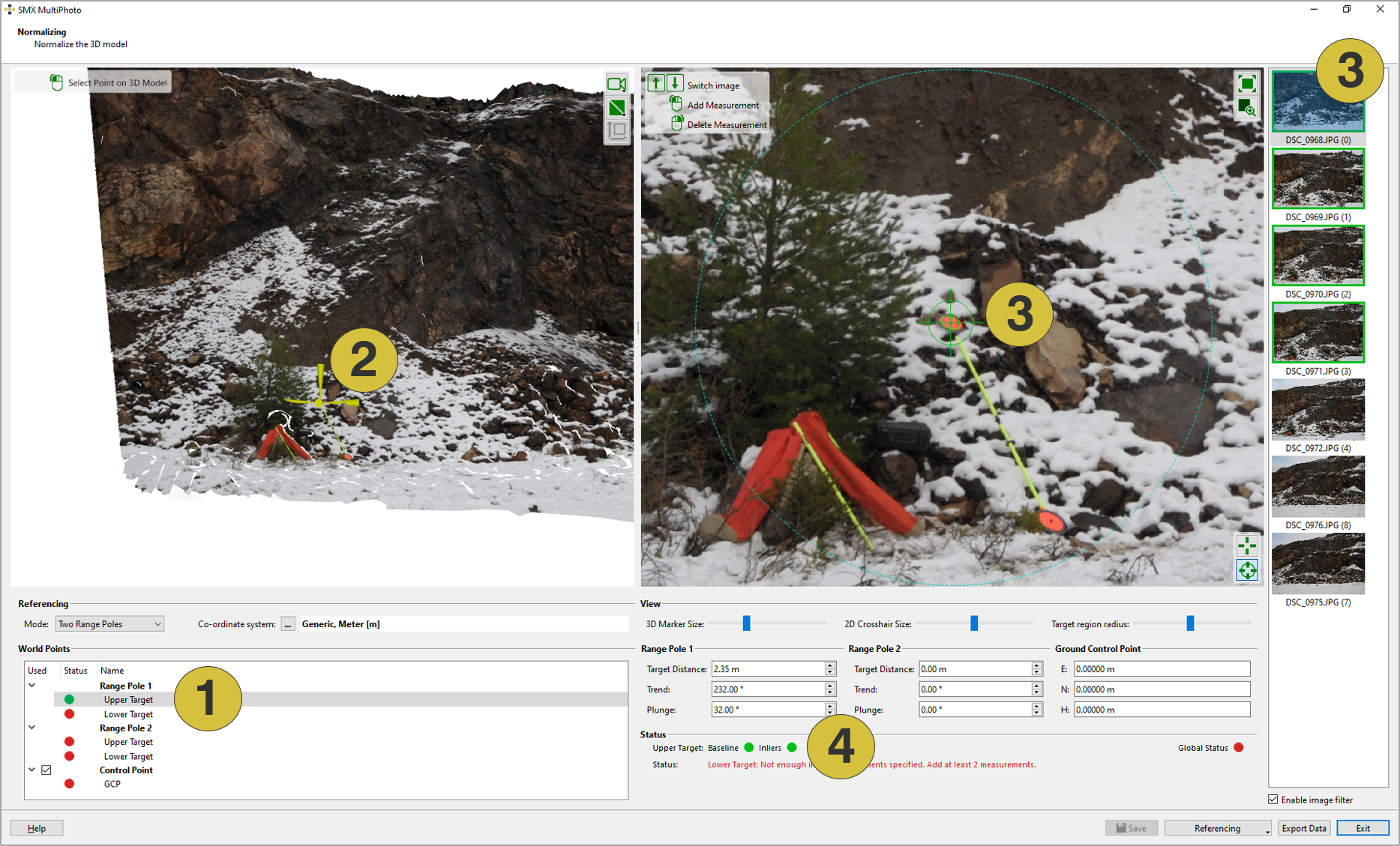
- Targets in the list
- Localization of the target in the 3D viewer
- Target in individual images
- Status of the individual targets
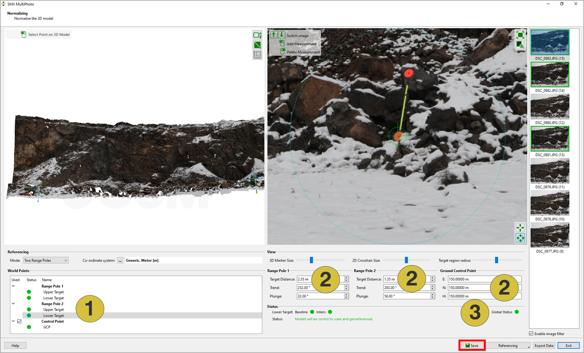
- Defined points
- Parameters for scaling and referencing
- Global Status