Trace
The Trace mode is used for annotating lineaments. A Trace measurement is a polygonal line following the object surface in 3D space. Its length is provided in terms of the Euclidean distance and along the surface. The Structure List reveals the Trace’s length along the surface. Traces are also used to determine the spacing of a Structure Set.
Standard operating procedure
- Activate “Measurements” in the toolbar of the Structure tab by clicking the corresponding radio button
- Click on the “Trace”
 icon or use the shortcut key “T”
 - Mark the Trace on the 3D model by clicking the left mouse button. A polygonal line is growing instantaneously.
- Finish the Trace measurement and continue the mapping by pressing the “Space” key or finish the Trace measurement by clicking “Enter” or by clicking the “Trace” icon. The length of the Trace is provided instantly in the Structure List
Edit the Trace measurement by a double click with the right mouse button on the item:
- Add a point by clicking the right mouse button
- Insert a point by holding “Ctrl” and clicking the right mouse button
- Delete a point by holding “Alt” and clicking the right mouse button
- Move a point by holding “Shift” and clicking the right mouse button
The below figure shows a Trace measurement following the trace on the rock surface. If the measurement is active, the defined points are marked with squares. The figure also shows the obtained orientation (see below) as a semi-transparent plane. The values are displayed at the associated entry in the Structure List.
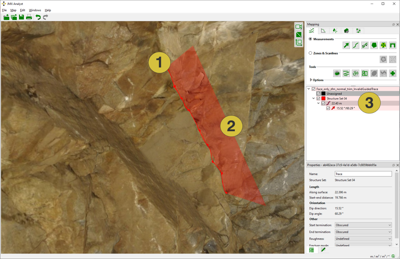
- Trace follows the rock surface
- Square indicates the plane forming the Trace and its orientation
- Length along the surface, dip direction, and dip angle
The below figure shows the Properties pane of Traces. The pane is opened in the context menu with “Show Properties” or by a click on “Windows | Properties” in the menu bar. The pane comprises the name of the Trace, information to which Structure Set the measurement belongs, values on the length, the orientation of the joint plane (if determined), the termination index, roughness and the fracture mode. The name of the Trace can be edited in order to use an intuitive name or for more detailed descriptions. Customized notes can be added to individual Traces in the Notes tab.
The termination index can be defined for the start and end points of the Trace. Following options are available:
- Obscured: End of Trace is obscured by blocks, scree, vegetation, etc. or by
extending beyond the limits of the exposed outcrop - Intact Rock: Trace terminates in intact rock material
- Discontinuity: Trace terminates at another discontinuity
The roughness is undefined by default. It can be defined as very rough, rough, planar, curved or polished in the Properties pane by using the corresponding pull down menu. In addition, the fracture mode is undefined by default. It can be defined as Extensional, Shear (dextral) or Shear (sinistral) in the Properties pane by using the corresponding pull down menu. .
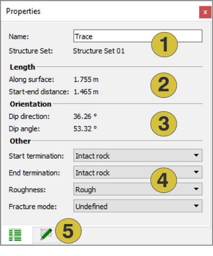
- Name of the Trace (editable) and Structure Set
- Length
- Mean orientation of the Trace
- Properties (editable)
- Notes
Trace Orientations
If a Trace has sufficient variation in depth, a plane is fitted (least squares) and instantly visualised by a rectangle cutting through the 3D model. The Orientation given by dip direction and dip angle is instantly shown in the Structure List. If the Trace polygonal has not enough depth variation for a reliable plane fitting, no Orientation is provided.
Context menu
- Edit
Add a point by clicking the right mouse button. Insert a point by holding “Ctrl” and clicking the right mouse button. Delete a point by holding “Alt” and clicking the right mouse button. Move a point by holding “Shift” and clicking the right mouse button - Edit (guided)
Expands the active Trace with a Guided Trace(see Chapter 4.5) by clicking the end position on the 3D model with the left mouse button - Add an Orientation
Adds a subordinate orientation to the Trace (if not already present). This orientation is a part of the Trace and has only restricted possibilities for modification. Only one orientation can be added to a Trace. - Add Discontinuity Model
Models the extent of a fracture by a finite plane - Set Colour
Defines a new colour for the Trace - Active
Activates (shows) and deactivates (hides) the selected item - Look at
Centers the Trace in the 3D viewer - Look at and Zoom
Centers and zoom the Trace in the 3D viewer - Delete
Deletes the selected Trace - Show Properties
Opens the Properties pane for the Trace - Move to
Moves the Trace to another Structure Set - Export
- Export Structural-Geologic Data as CSV Exports the measurement as “.csv” file
- Export as DXF Exports the measurement as ”.dxf” file
- Export as VRML Exports the measurement as ”.vrml” file