Blast Site Markers Overview
The available modes can be used to scale a generic 3D model to metric dimensions within a local coordinate system. In addition, the software allows the model to be rotated to an externally determined azimuth using a Reference Line. Ground Control Points (GCPs) can also be imported to further improve georeferencing and spatial accuracy.
The Blast Site Marker Mode the following parameters:
- Upper Target of the Left Range Pole
- Lower Target of the Left Range Pole
- Upper Target of the Right Range Pole
- Lower Target of the Right Range Pole
- Target distance and height of Range Poles
- Left Floor Level Marker (set from Left Range Pole, can be adjusted)
- Right Floor Level Marker (set from Right Range Pole, can be adjusted)
- Right Delimiter
- Left Delimiter
- Target height of Delimiter
- Azimuth of Reference Line (optional)
- Top Level Surface Marker (optional)
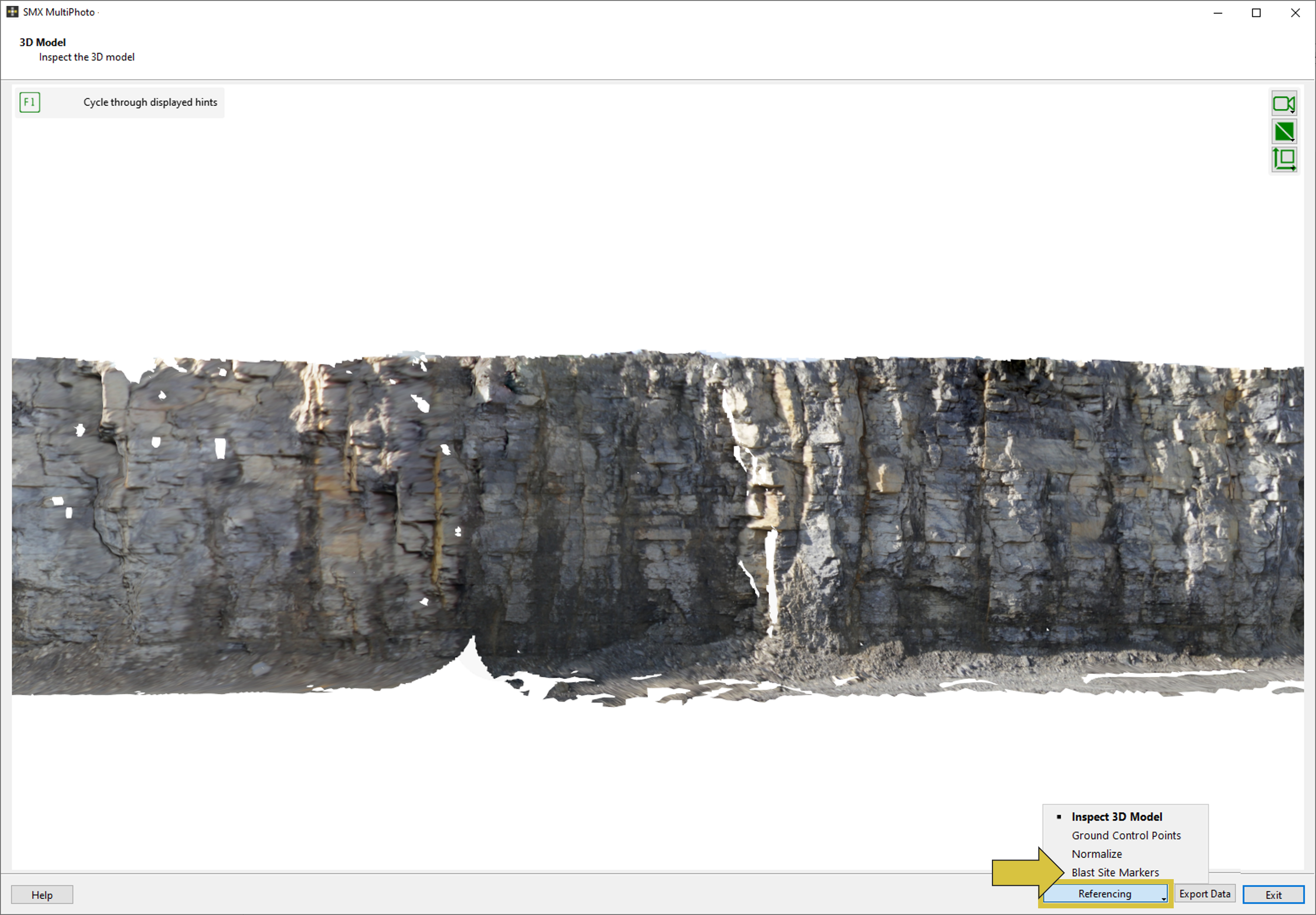
To enter the interface the button “Referencing” and “Blast Site Markers” from the pull down menu has to be selected.
User Interface
The user interface Blast Site Marker of the MultiPhoto comprises the 3D viewer and the list of Blast Site Marker on the left hand side. On the right hand side it consists of a viewer showing the currently selected image for referencing and corresponding partner images.
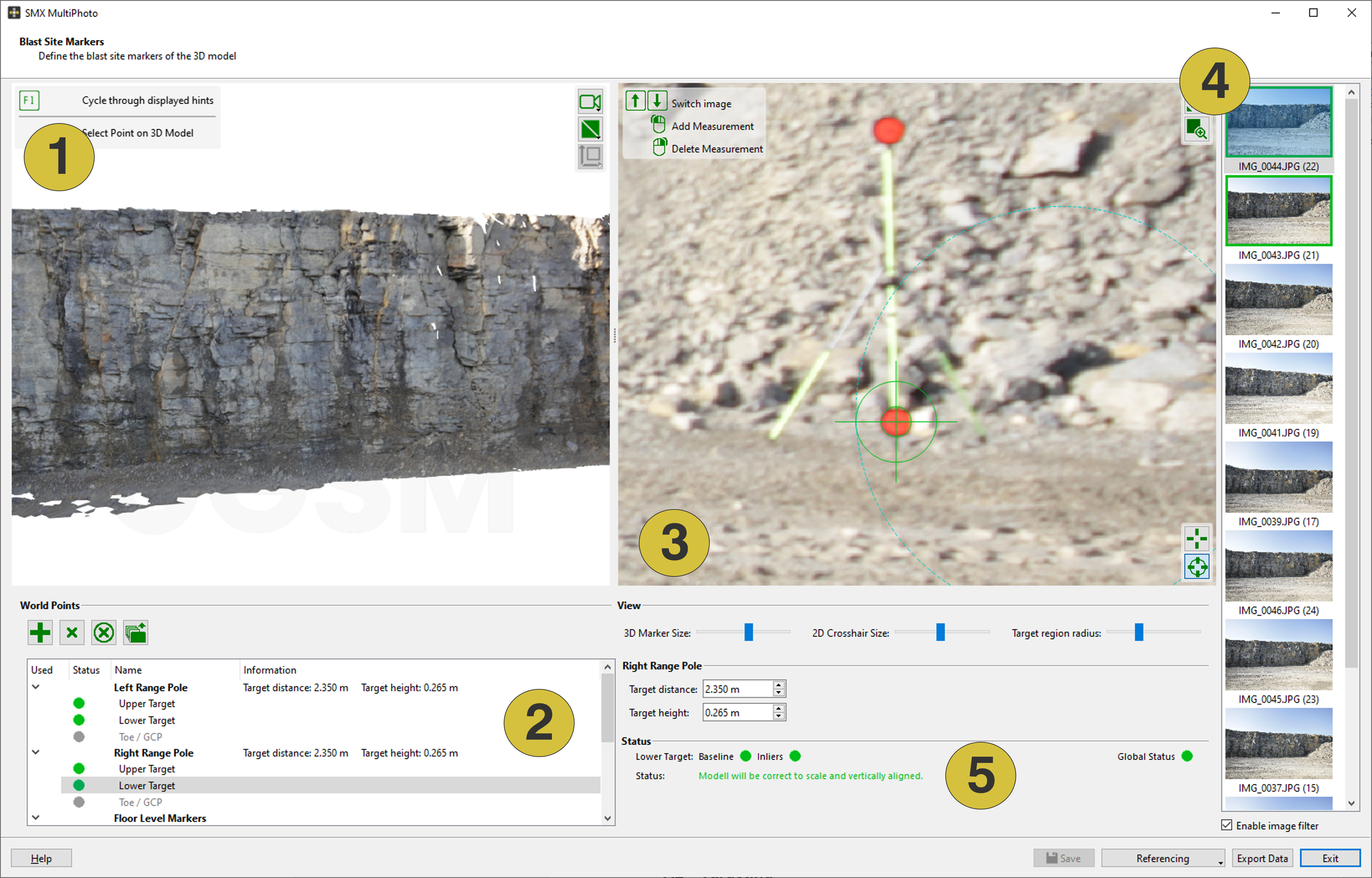
- 3D viewer
- List of markers
- Viewer with selected image
- Partner images
- Status
Features
World Points
 Adds - Adds Top Level Surface Marker
 Remove - Removes the selected Top Level Surface Marker
 Remove All - Removes all Top Level Surface Marker
 Load Ground Control Points - Import co-ordinates from a text based file (“.csv”, “.txt”, “.dat”, “.prt”)
View (2D Viewer)
 View full image - Fits the size of the image to the size of the viewer
 Zoom to Target Region - Zooms to the target region
 Manual Target Mode - Activates manual targeting
 Automatic Target Mode - Activates automatic targeting
- Sliders
- 3D Marker Size - Changes the size of the target in the 3D viewer
- 2D Crosshair Size - Changes the size of the crosshair in the 3D viewer
- Target Region Radius - Defines the zoom (radius) to the target region
- Enable Image Filter - De/activates the image filter. Enabled filter: Images of the currently clicked position in the 3D viewer are listed. Disabled filter: All images used for 3D model generation are listed.
Status
The user receives information on the configuration of each individual marker set (Baseline and Inliers), the current status of the procedure, and guidance on the next step to perform.
Feedback on individual markers:
- Baseline: Indicates whether the selected measurements provide sufficient baseline
- Inliers: Indicates whether there are enough valid image measurements
Global Status is indicated using colour coding, with the following meanings:
- Red: The configuration contains errors and scaling cannot be performed. The status provides instructions on how to correct it.
- Orange: The configuration shows warnings. Scaling may be possible, but the data should be checked for validity first.
- Green: The configuration is valid.