Region Grow
The Region Grow mode is used for annotating area based structures (e.g. discontinuity surfaces). It is a semi-automatic mode intended to discriminate planar patches on the 3D model. A Region Grow consists of a closed polygonal line that follows a discontinuity surface or any arbitrary portion of the surface. The size of the Region Grow is provided in terms of the spatial area in the Structure List.
Standard operating procedure
- Activate “Measurements” in the toolbar of the Structure tab by clicking the corresponding radio button
- Click on the “Region Grow”
 icon or use the shortcut key “R”
 - Click on an arbitrary point (seed point) on the 3D model with the left mouse button and
- desire the extension of the Region Grow (Sphere of Influence outlined as a planar patch around the seed point) holding “Shift” and moving the mouse up (increase the extension) or down (decrease the extension) on the 3D model.
- desire the Growing Distance by holding “Ctrl” and moving the mouse up (far) or down (short) on the 3D model.
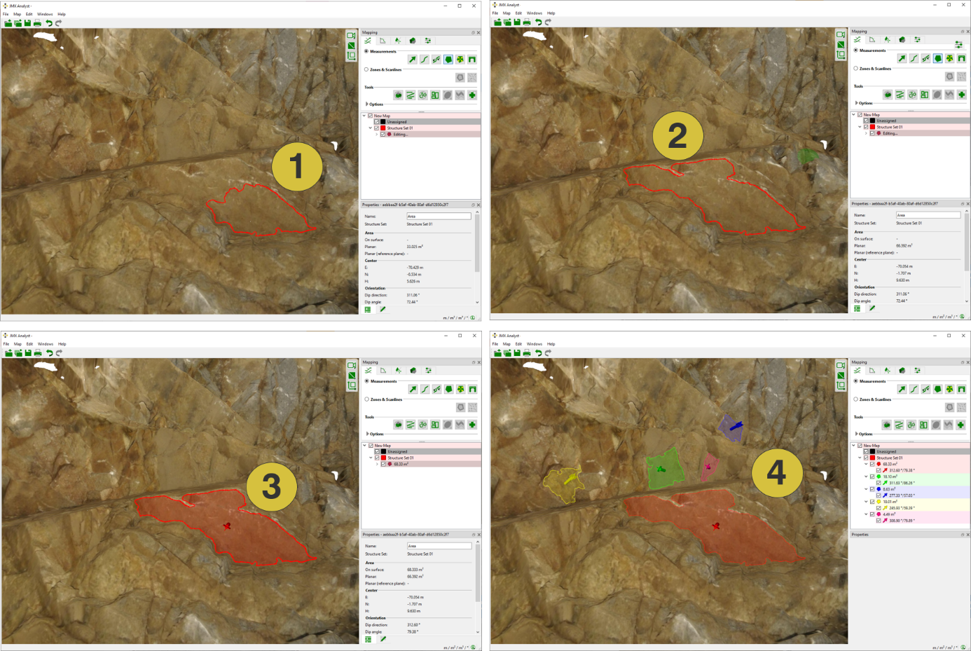
- Release the mouse and an area automatically pops up enclosing a planar patch.
- Expand the Region Grow by holding “Ctrl” and clicking outside the polygon on the 3D model with the left mouse button.
- Finish the Region Grow measurement and continue the mapping by pressing the “Space” key or finish the Region Grow measurement by clicking “Enter” or by clicking the “Region Grow” icon. The Region Grow is automatically shaded and the Orientation (i.e. mean orientation of the surface normal) is added. The size of the Region Grow is provided in terms of an Area the Structure List.
Edit the Region Grow measurement by a double click with the right mouse button on the item:
- Insert a point by holding “Ctrl” and the clicking right mouse button
- Delete a point by holding “Alt” and the clicking right mouse button
- Open the area by holding “Alt” and the clicking right mouse button and a click on the polygon
- Move a point by cli holding cking “Shift” and the clicking right mouse button
If the polygon cannot be closed at a certain position, the area will be outlined as “Invalid Area” in the Structure Set list. The position is highlighted by a yellow spot in the 3D viewer and the position has to be adapted by the user to finish the area measurement.
The Properties pane for the Region Grow is identical as for Areas.
Characteristics of a Region Grow
The anatomy of a Region Grow is identical to the one of the Area. In contrast, it uses an ingenious algorithm to discriminate planar patches around seed points. The seed point is a point on the 3D model which has been defined by the left mouse button. An initial orientation is assigned to the seed point. The surrounding of the seed point is considered as planar if it complies with two criteria:
- The mean orientation of the subset must not deviate a certain angle from the initial seed point orientation
- The location of the subset must not be located at a certain offset from the seed point location
Rock surfaces are usually non-planar, i.e. they show a certain roughness or curvature. The criteria have been calibrated to enable the Region Grow function for a wide set of different rock mass properties.
Consideration of local roughness of the region
The roughness of the region influences the effectiveness of the planarity criteria. It is possible to control the size of the volume in which the roughness is sampled. In general and for best results, the sampled volume should stand for the global roughness of the analysed regions.
Sampling of region roughness
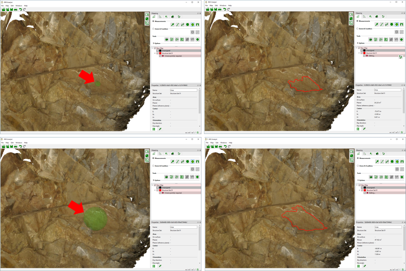
If the user clicks the seed point on the region and a green sphere appears (e.g. figure top left). The green sphere indicates the volume used for sampling the region roughness. Regions of the 3D model inside the green sphere are used for deriving the roughness. The sphere can be downsized or enlarged by holding “Ctrl” and scrolling the middle mouse wheel (below) shows a downscaled sphere and the corresponding result of the Region Grow and an enlarged sphere and the corresponding result of the Region Grow. The Region Grow is launched once the left mouse button has been clicked.
Growing Distance
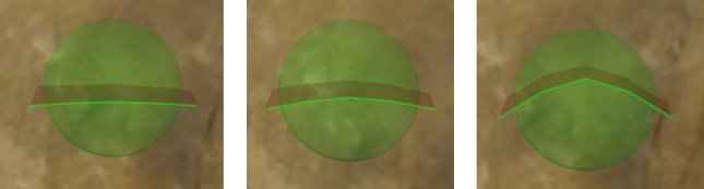
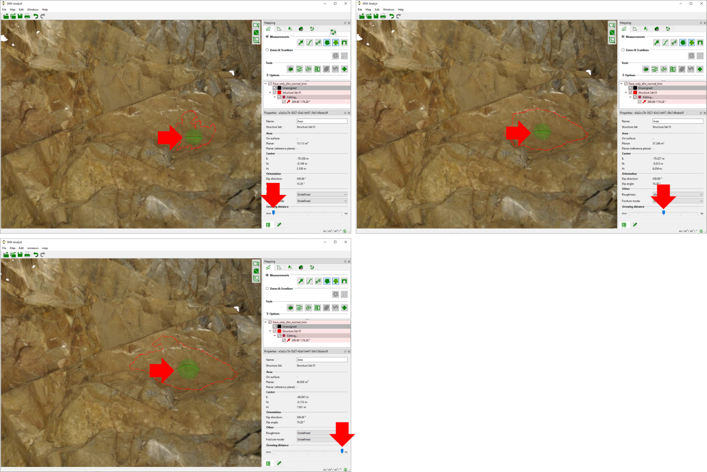
The Growing Distance is controlled by an insert which appears upon activating the “Region Grow” in the Properties pane or by holding “Ctrl” and scrolling the mouse wheel. The user can select five levels between “Short” and “Far”. The Growing Distance influences the thresholds applied for the planarity criteria (orientation and offset criteria). Below figure shows the results for automatically grown area with a “Short”, intermediate, and “Far” Growing Distance.
The modification of the Growing Distance is indicated by polygon visualized together with the sphere of influence during editing. A straight polygon indicates a short Growing Distance whereas a stepwise curved one indicates an increased Growing Distance (intermediate too far).
The context menu of the Region Grow is identical to the context menu of the Area.