Guided Trace
The Guided Trace mode is used for annotating lineaments. It is a semi-automatic mode by clicking the start and end point of a joint trace. Image and graph processing algorithms provide the course of the trace and visualizes the trace on the 3D model. Its length is provided in terms of the Euclidean distance and along the surface. The Guided Trace comply with a Trace measurement and it is outlined as Trace in the Structure List. The Structure List reveals the Guided Trace’s length along the surface. Guided Traces are also used to determine the spacing of a Structure Set.
Standard operating procedure
- Activate “Measurements” in the toolbar of the Structure tab by clicking the corresponding radio button
- Click on the “Guided Trace”
 icon or use the shortcut key “G”
 Add the start and the end point of the Guided Trace on the 3D model by clicking the left mouse button. A polygonal line surrounded by a cylinder is shown instantaneously on the 3D model. Optionally, insert a guidance point by holding “Ctrl” and clicking the left mouse button and delete the last added guidance point by holding “Alt” and clicking the right mouse button.
Continue a Guided Trace by clicking the left mouse button on the 3D model during first editing or use the command “Edit (guided)” in the context menu after first editing. A polygonal line is growing instantaneously when clicking on the 3D model.- Adapt the course of the trace by adjusting the cylinder´s width (sphere of influence) by holding “Shift” and scrolling the mouse wheel. A narrow cylinder results in a straight trace, whereas the trace is allowed to deviate from a straight course by increasing the cylinder´s width.
- Finish the Guided Trace measurement and continue the mapping by pressing the “Space” key or finish the Guided Trace measurement by clicking “Enter” or by clicking the “Guided Trace” icon. The length of the Guided Trace is provided instantly in the Structure List.
Edit the Guided Trace measurement by a double click with the right mouse button on the item:
- Add a point by clicking the right mouse button
- Insert a point by holding “Ctrl” and clicking the right mouse button
- Delete a point by holding “Alt” and clicking the right mouse button
- Move a point by holding “Shift” and clicking the right mouse button
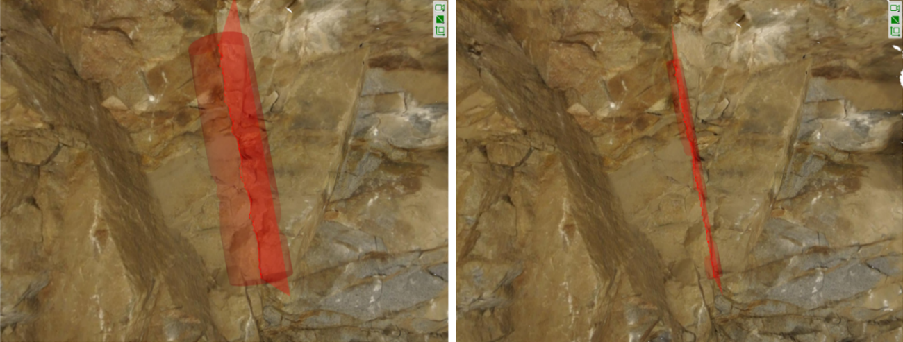
The below figure shows a Guided Trace measurement following the trace on the rock surface. If the measurement is active, the defined points are marked with squares. The figure also shows the obtained orientation (see below) as a semi-transparent plane. The values are displayed at the associated entry in the Structure List.
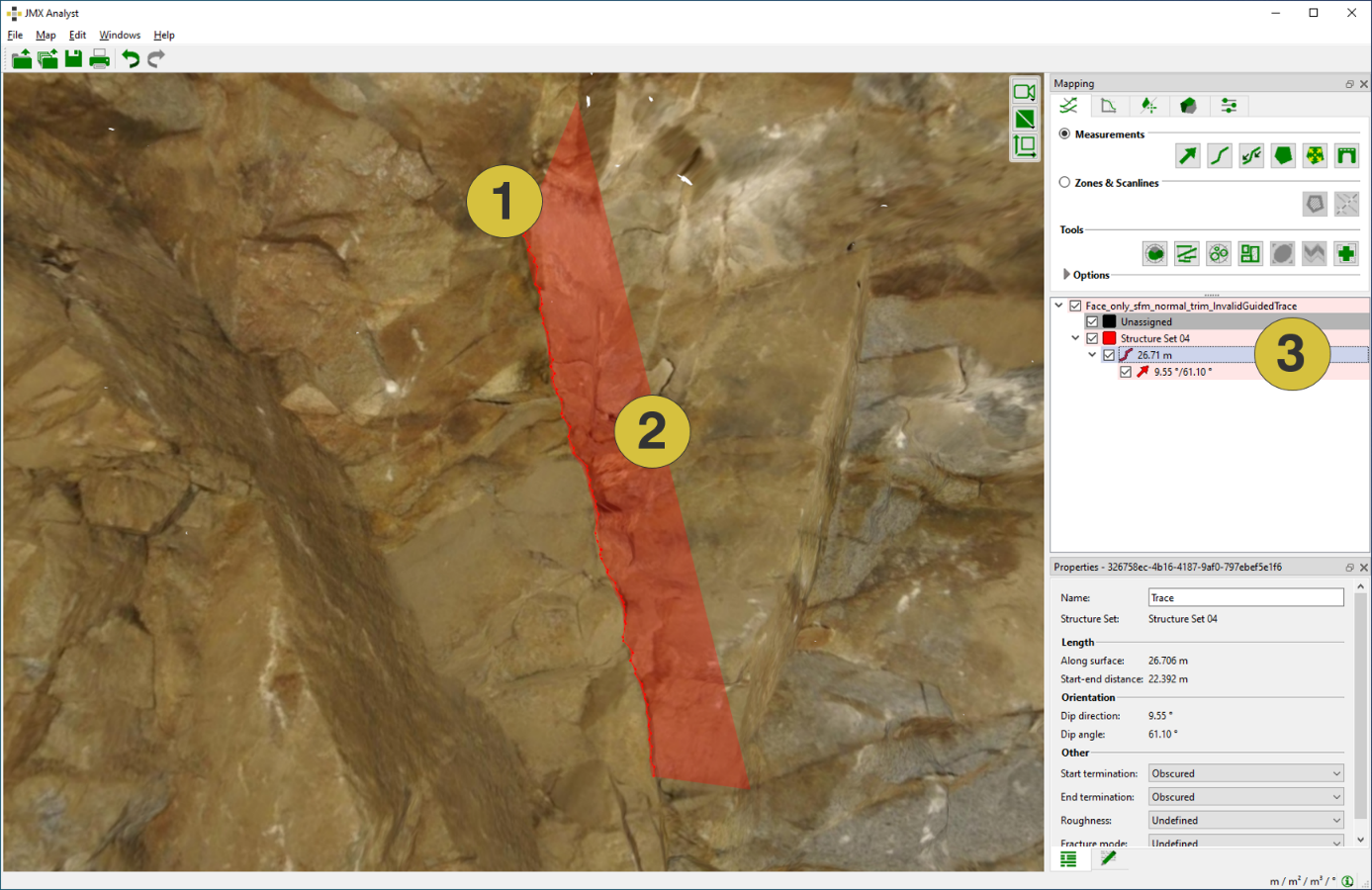
- Trace follows the trace along the rock surface
- Square indicates the plane forming the Trace and its orientation
- Length along the surface, dip direction, and dip angle
Guided Trace Orientations
If a Guided Trace has sufficient variation in depth, a plane is fitted (least squares) and instantly visualised by a spatial rectangle cutting through the 3D model. The Orientation given by dip direction and dip angle is instantly shown in the Structure List.
The Properties pane and the context menu for the Guided Trace are identical as for Traces and is described in the Trace topic.