Section
A Section in the Analyst is a planar polygonal line formed by the intersection of a cutting plane and the 3D model. The cutting plane is defined by its position (three co-ordinates) and orientation (Inclination and Strike Direction). The software proposes a cutting plane after first editing. The user can edit the section type, the position and the orientation subsequently.
Standard operating procedure
- Click on the “Section”
 icon in the toolbar of the Geometry tab or use the shortcut key “S”. A Section including its cutting plane appears in the center of the 3D model. The used Section type is the same as with the last call of the function. The Section is active and editable.
 - Define the configuration of the Section in the Properties pane:
- Select the type of the Section: “General”, “Vertical”, and “Horizontal” Section
- Move Section to the target position on the 3D model. Click with the left mouse button at the desired position on the 3D model or drag the Section there. The Reference Point on the plane is marked with a black dashed line.
- If necessary, adjust the orientation of the Section. Change “Inclination” and/or “Strike direction” of the cutting plane by entering the desired values in the editable fields or by scrolling the mouse wheel.
- Confirm the Section and add another Section by pressing the “Space” key or finish the Section by clicking “Enter” or by clicking the “Section” . The Section is provided instantly in an individual list in the Geometry tab.
Edit the Section by a double click with the right mouse button on the item and set a new position of the Section by clicking the left mouse button.
The below figure shows the Properties pane for Sections. The pane is opened in the context menu with “Show Properties” or by a click on “Windows | Properties” in the menu bar. It comprises the name of the Section which can be edited in order to use an intuitive name or for more detailed descriptions and allows fast and instant editing of Section types and orientations. The Section type, i.e. General Section, Vertical Section or Horizontal Section can be selected by the activation of the corresponding radio button. In addition, editing the orientation of the Section in terms of inclination and strike direction is provided. The button  180° changes the strike direction of the Section by 180°. The dialog also provides information about the position of the cutting plane. The plot of the Section can be printed or saved as “pdf” by a click on the “Print” button. Customized notes can be added to individual Sections in the Notes
 tab.
tab.
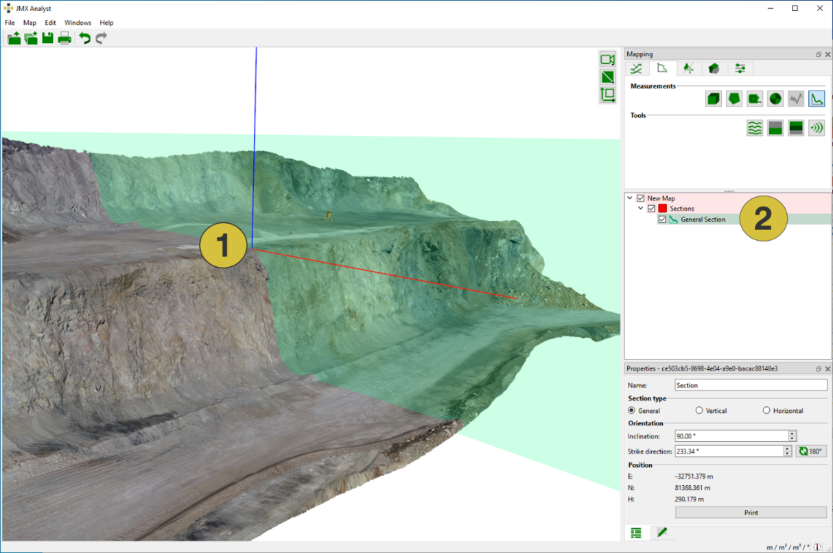
- General Section
- Entry in the list
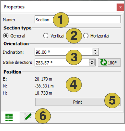
- Name of the Section (editable)
- Type of Section (editable)
- Orientation parameters (editable)
- Position
- Print plot
- Notes (editable)
Section Types
- The General Section is formed by an arbitrarily orientated cutting plane whose orientation the user controls with inclination and strike direction. General Sections appear in cyan on the 3D model.
- The Vertical Section is formed by a vertical Cutting Plane. The user controls the strike direction while inclination remains at 90°. Vertical Sections appear in magenta on the 3D model.
- The Horizontal Section is formed by a horizontal Cutting Plane. The user controls the strike direction while inclination remains at 0°. Vertical Sections appear in blue on the 3D model.
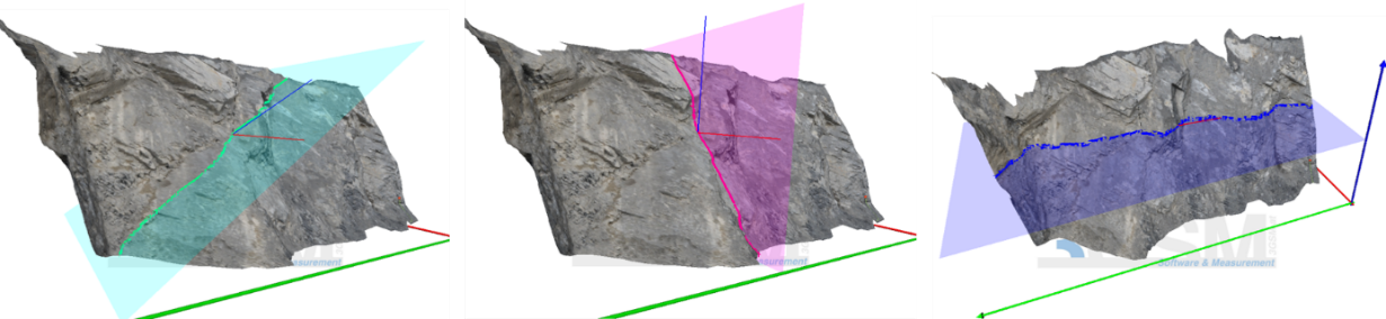
Editing a Section
- Changing the position of a Section: The position of is changed by moving the Section within the 3D viewer (in the Edit mode) while keeping the left mouse button pressed. The function “Modify Section” is called via the context menu of the Section. The new position is confirmed by pressing the return key or middle mouse button.
- Changing the orientation of a Section: The orientation is defined by “Inclination” and “Strike Direction”. Inclination is changeable for General Sections only. Strike direction is changeable for General, Vertical, and Horizontal Section. The values are edited in the section Properties pane:
- by entering the desired values
- by turning the mouse wheel in the Edit mode
- simple turning affects strike direction
- turning together with pressing the “Ctrl” key affects inclination
- by using the scrolling mechanism
The new orientation is confirmed by pressing the return key or middle mouse button.
Cutting Plane
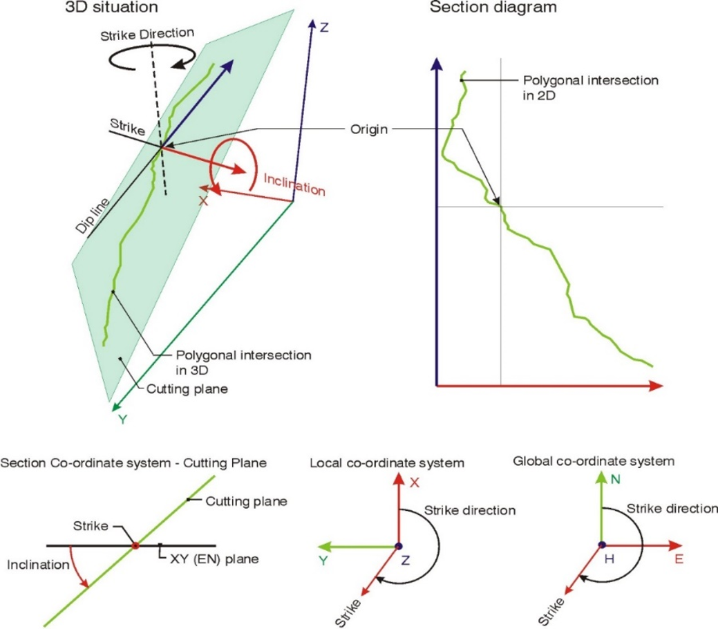
The Cutting Plane carries a defined co-ordinate system as is shown below. It comprises the strike line (red), the negative dip line (blue), and the corresponding upward normal vector (not shown). The strike line remains in the Cutting Plane and is always horizontal. It is defined by the strike direction for all three, the General Section, Vertical Section, and Horizontal Section. The strike directionis the clockwise angle measured from the x-axis (local co-ordinate system of 3D model) / N-axis (global co-ordinate system of 3D model). Inclination is the angle measured from the xy-plane (EN-plane) downwards about the strike line. It is editable for the General Section only and predefined for the Vertical (90°) and Horizontal (0°) Section. The origin of the cutting plane’s co-ordinate system is indicated by a black dashed vertical line (parallel to z / H-axis). The origin is always located on the 3D model, thus the intersection between Cutting Plane and 3D model always contains the origin. The following figure shows the Cutting Plane and the associated co-ordinate system in Analyst.
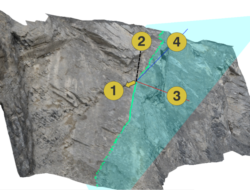
- Origin = Reference Point
- Reference Point indicator (black dashed line)
- Axis referring to the strike direction (red)
- Axis referring to the negative dip direction (blue)
Plot and export of Sections
The plot of a Section (Plot pane see below) is a parallel projection of the cutting plane’s co-ordinate system. The viewing direction is perpendicular to the cutting plane against the upward normal vector of the cutting plane’s co-ordinate system. The projected strike line forms the abscissa and the negative dip line the ordinate of the section diagram. The origin of the Section diagram is contained within the polygon (except for geo-referenced vertical Sections where it shows the geo-referenced height instead of zero height). The Plot pane is opened in the context menu “Show Plot” or by a click on “Windows | Plot” in the menu bar. The profile of the Section can be shown exaggerated and not exaggerated depending on whether the scale switch is selected or unselected.
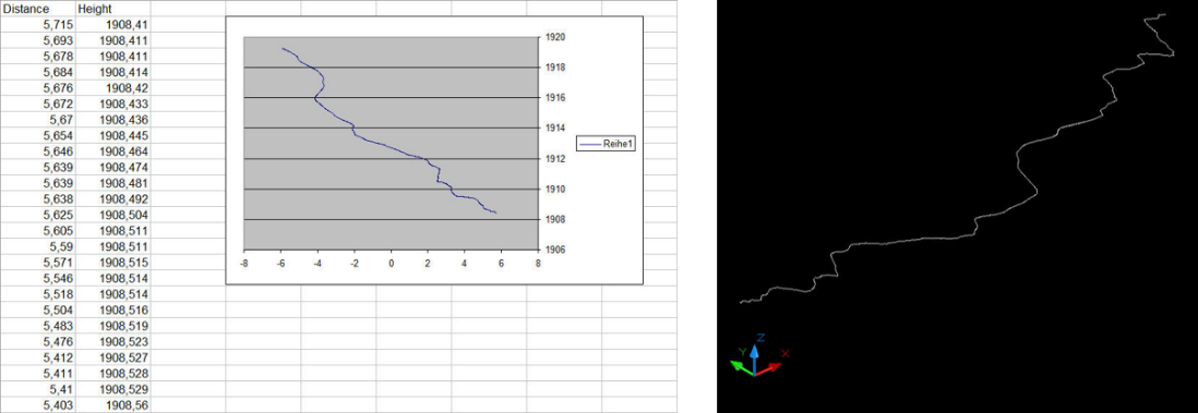
The data of the profile can be exported by clicking the “Export” button. The export is possible in “.csv” and “.dxf” format. The exported data comprises the polygonal line corresponding to the intersection between cutting plane and 3D model. Figure 95 shows the exported Section in “.csv” format transferred to a spreadsheet program (2D) and in “.dxf” format visualised in a dxf-viewer (3D). For the “.dxf” export it is necessary to define whether it shall be original 3D or transformed 2D. The 3D export considers the original intersection polygon in 3D co-ordinates. The 2D export transforms the data into a horizontal plane leaving the z co-ordinate in zeros. The plot of the Section can be printed or saved as “pdf” file by a click on the “Print” button in the Properties pane.
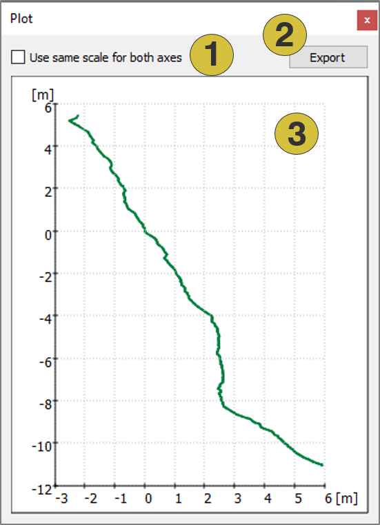
- Scale width: Enable / disable the same scale for both axes
- Export the profile
- Sketch of profile
Context menu
- Edit
Move the Section by clicking the left mouse button - Active
Activates (shows) and deactivates (hides) the selected item - Show Plot
Opens the Plot pane for Sections - Look at
Centers the Section in the 3D viewer - Look at and Zoom
Centers and zoom the Section in the 3D viewer - Delete
Deletes the selected Section - Show Properties
Opens the Properties pane for Sections - Export
- Export as DXF - Exports the Section as ”.dxf” file
- Export as VRML - Exports the Section as ”.vrml” file