Export Map
Following options are available:
- Export to Dips - “Map| Export | Export Map as DXF. Writes a “3gdps” filethat allows for the exchange of structural-geologic mapping data between the Analyst and Rocscience Dips software.
Example:
SET_START
SetID,SetName,SetColour,meanDip,meanDipDirection,sphericalAperture,FisherConcentratio
degreeOfOrientation,coneOfConfidence,confidenceLevel,weightIndicator,meanSpacing,
standardDeviationSpacing,meanTraceLength,standardDeviationTraceLength
0,”unassigned”,000000,-1.0,-1.0,-1.0,-1.0,-1.0,-1.0,-1.0,0,-1.0,-1.0,-1.0,-1.0
1,”StructureSet01”,ff0000,26.5,283.5,0.84,4705.26,99.9,3.64,95.0,0,3.15,1.85,13.5,2.15
2,”My Set #2”,0101df,21.4,200.72,32.72,3.42,70.78,0.0,95.0,0,-1.0,-1.0,-1.0,-1.0
SET_END
GRID_START
Dip,DipDirection,SetID,Colour,X(Easting),Y(Northing),Z(Elevation),Persistence
45.000,120.000,0,000000,100981.000,60345.000,1056.000,10.000
26.000,285.000,1,ff0000,100450.000,60120.000,1075.000,15.000
27.000,282.000,1,ff0000,100453.000,60125.000,1070.000,12.000
28.000,280.000,2,0101df,100451.000,60124.000,1065.000,13.000
45.000,160.000,2,58fa58,100481.000,60138.000,1045.000,-1.0
GRID_END - DXF export - “File | Export | Export Map as DXF”: Writes a “.dxf” file of the geometry of selected Annotation Elements from the Structure List
- VRML export - “File | Export | Export Map as VRML”: Writes a “.vrml” 2.0 file containing data on the Annotation Elements from the Structure List
- CSV export (Open Pit) - “File | Export | Export Traces to Open Pit”: Writes a “.csv’” file of Trace parameters for Open Pit. Structure of Open Pit Simulator data file for Trace parameters:
"*Use?","Dip","deltaDip","DDir","DeltaDDir","Diam",”Spacing","Phi","Coh","ObsTraces","MaxJnte","Domain"
12 numerical values - CSV export:
- Scanline - “File | Export | Export Spacing Scanline Data as CSV”: Writes a “.csv” file of Scanline parameters
- Structural data: “File | Export | Export Structural Geologic Data as CSV”: Writes a “.csv” file of structural geologic data such as joint areas and traces. The export provides geometric information and reference to the measurement. The exported data can be configured by the user. The following options are available:
- Unique Identifier
- Name of the measurement
- Structure set of the measurement
- Coordinates – three columns (x, y, z or Easting, Northing, Height)
- Orientation – two columns (dip direction, dip angle)
- Length of the measurement (for Traces) | equivalent length of the measurement (for Areas)
- Area on surface
- Planar area
- Area partitioning data: “Map | Export | Export Area Partitioning Data as CSV”
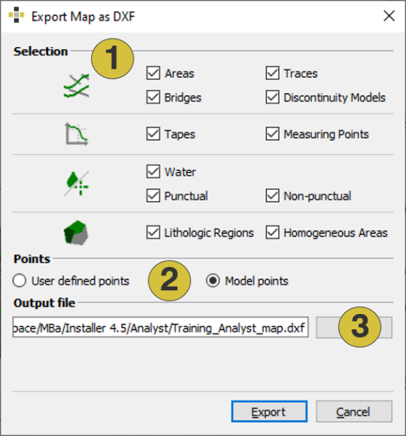
- Exported annotation types
- Model or user-defined points
- Folder and file name
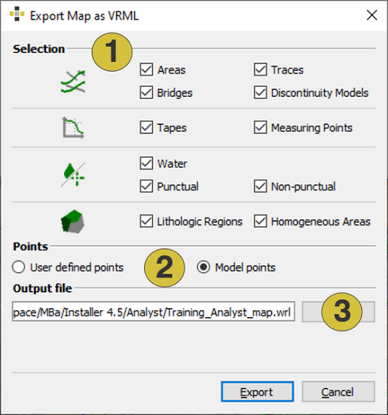
- Exported annotation types
- Model or user-defined points
- Folder and file name
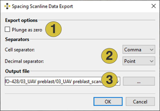
- Defines the plunge of the Scanline as zero
- Type of separators
- Folder and file name
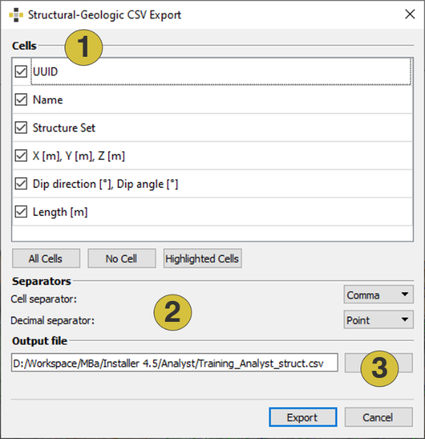
- Exported cells
- Type of separator
- Folder and name
Export of Discontinuity Models
Following options are available:
- DXF Export: The shape of Discontinuity Models can be exported as “.dxf” file format. The export is available in the selected element´s context menu (Discontinuity Model and Structure Set) by selecting “Export | Export Discontinuity Models as DXF”. The export is also available in the context menu of individual Discontinuity Models open by selecting the item in the Structure Set list and clicking the right mouse button. The export includes the shape of the discontinuity as a polygon. Following attributes “Extended Data” (metadata) can be added to the export:
- Dip direction of Trace / Area
- Dip angle of Trace / Area
- Length of Trace / equivalent length of Area
The structure of the “.dxf” file for “Extended data” is as follows:
1001 Code for registered application name for extended data
GSM Application name
1040 Code for extended data floating point value
178.33 Dip direction of Trace / Area
1040 Code for extended data floating point value
70.33 Dip angle of Trace / Area
1041 Code for extended data distance value
123.45 Length of the Trace / equivalent length of the Area
For further information please refer to: AutoCAD 2012 - DXF Reference (https://images.autodesk.com/adsk/files/autocad_2012_pdf_dxf-reference_enu.pdf)
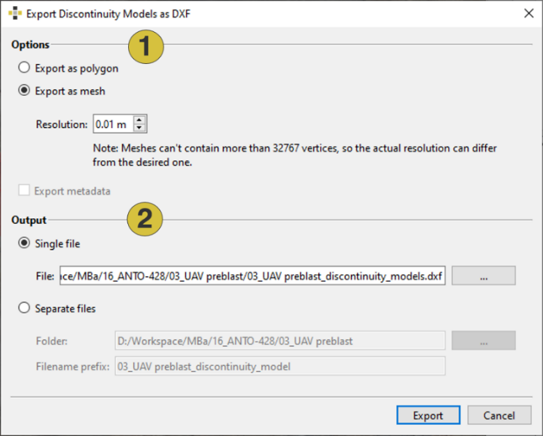
- Options (polygon or mesh)
- Output options
CSV Export: “File | Export | Export Discontinuity Models as CSV”: Writes a “.csv” file of Discontinuity Model data. The export is also available in the context menu of individual Discontinuity Models open by selecting the item in the Structure Set list and clicking the right mouse button. The export provides geometric information and reference to the measurement. The exported data can be configured by the user. The following options are available:
- Unique Identifier
- Name of the measurement
- Structure set of the measurement
- Coordinates – three columns (x, y, z or Easting, Northing, Height)
- Orientation – two columns (dip direction, dip angle)
- Type (shape): circle, ellipse, rectangle
- Parameters (A, B, epsilon)
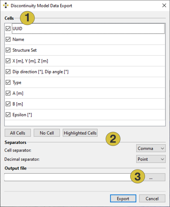
- Exported cells
- Type of separator
- Folder and name
Export of Discontinuity Surfaces
Discontinuity Surfaces can be exported as “.dxf” file format. The export is available in the selected element´s context menu (Discontinuity Surface and Structure Set) by selecting “Export | Export Discontinuity Surfces as DXF”. The export is also available in the context menu of individual Discontinuity Surface opened by selecting the item in the Structure Set list and clicking the right mouse button as well as in the menu bar “File | Export | Export Discontinuity Surface as DXF”.
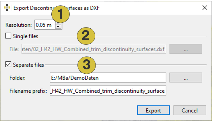
- Mesh resolution
- Export to single files
- Export to separate files